Basic Flowchart Symbols and Meaning


UML Class Diagram Example for Transport System

 Entity-Relationship Diagram (ERD)
Entity-Relationship Diagram (ERD) solution extends ConceptDraw PRO software with templates, samples and libraries of vector stencils from drawing the ER-diagrams by Chen's and crow’s foot notations.
Use the Best FlowChart Tool for the Job

JSD - Jackson system development

Simple & Fast Diagram Software


Flow chart Example. Warehouse Flowchart

 Computer and Networks Area
The solutions from Computer and Networks Area of ConceptDraw Solution Park collect samples, templates and vector stencils libraries for drawing computer and network diagrams, schemes and technical drawings.
 Computer Network Diagrams
Computer Network Diagrams solution extends ConceptDraw PRO software with samples, templates and libraries of vector icons and objects of computer network devices and network components to help you create professional-looking Computer Network Diagrams, to plan simple home networks and complex computer network configurations for large buildings, to represent their schemes in a comprehensible graphical view, to document computer networks configurations, to depict the interactions between network's components, the used protocols and topologies, to represent physical and logical network structures, to compare visually different topologies and to depict their combinations, to represent in details the network structure with help of schemes, to study and analyze the network configurations, to communicate effectively to engineers, stakeholders and end-users, to track network working and troubleshoot, if necessary.
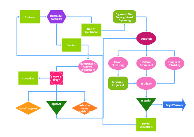
"The Process Flow Chart provides a visual representation of the steps in a process. ...
When to Use:
One of the first activities of a process improvement effort is constructing a flowchart. It provides the following benefits:
1- It give you and everyone a clear understanding of the process.
2- Facilitates teamwork and communication.
3- Helps to identify non-value-added operations."
[bexcellence.org/ Flow-Chart.html]
This TQM diagram example shows a business process that can be then analyzed to improve the effectiveness and diagnose quality issues that require resolution.
This example was created using the ConceptDraw PRO diagramming and vector drawing software extended with the Total Quality Management (TQM) Diagrams solution from the Quality area of ConceptDraw Solution Park.
TQM diagram
Influence Diagram

UML Use Case Diagram Example Registration System

 ConceptDraw Solution Park
ConceptDraw Solution Park collects graphic extensions, examples and learning materials
- Draw A Diagram Of Various Means Of Transportation
- Simple Diagram Of Means Of Transportation
- UML Class Diagram Example for Transport System | Flow chart ...
- Show Diagram Of Types Of Transportation
- Basic Flowchart Symbols and Meaning | Use the Best FlowChart ...
- Flow chart Example. Warehouse Flowchart | UML Class Diagram ...
- Data Flow Diagram For Bus Transport Service Management System
- Basic Flowchart Symbols and Meaning | Audit Flowchart Symbols ...
- Diagram Of Means Of Transportation
- Transport Management Flow Chart In Companies
- Basic Flowchart Symbols and Meaning | Design Pictorial ...
- UML Class Diagram Example for Transport System
- How To Draw Flow Diagram Showing Means Of Transportation
- Import And Export Management System Er Diagram
- Aerospace and Transport | Event-driven Process Chain Diagrams ...
- UML Composite Structure Diagram | UML Class Diagram Example ...
- Basic Flowchart Symbols and Meaning | Flow chart Example ...
- Flow chart Example. Warehouse Flowchart | UML Class Diagram ...
- Diagram Of Roundabout In Traffic Road Sign
- Rail transport - Design elements | UML Class Diagram Example for ...