HelpDesk
How to Draw Geometric Shapes

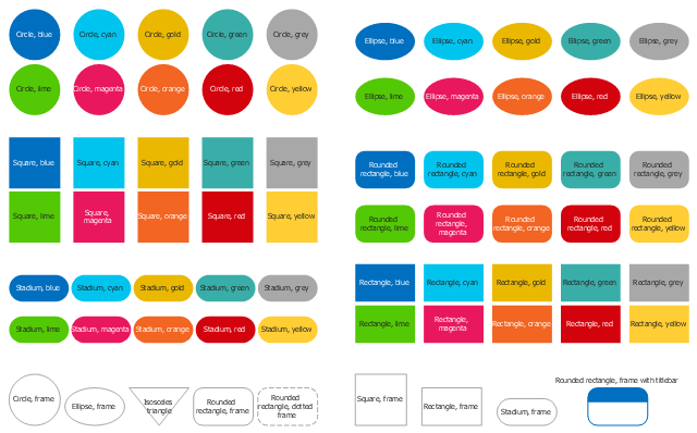
The vector stencils library "Cloud shapes" contains 69 geometric shapes.
Use it to design your cloud computing diagrams and infographics with ConceptDraw PRO software.
"The essence of a diagram can be seen as: ...
- with building blocks such as geometrical shapes connected by lines, arrows, or other visual links." [Diagram. Wikipedia]
The geometric shapes example "Design elements - Cloud shapes" is included in the Cloud Computing Diagrams solution from the Computer and Networks area from ConceptDraw Solution Park.
Geometric shapes for cloud computing diagrams
Basic Flowchart Symbols and Meaning


ERD Symbols and Meanings


The vector stencils library "Dimensioning and tolerancing" contains 45 symbols of geometric dimensions and mechanical tolerances, geometric symbols, callouts, and text boxes and inserts.
Use these geometric dimensioning and tolerancing (GD&T) shapes to create annotated mechanical drawings.
"Geometric dimensioning and tolerancing (GD&T) is a system for defining and communicating engineering tolerances. It uses a symbolic language on engineering drawings and computer-generated three-dimensional solid models that explicitly describes nominal geometry and its allowable variation. It tells the manufacturing staff and machines what degree of accuracy and precision is needed on each controlled feature of the part. GD&T is used to define the nominal (theoretically perfect) geometry of parts and assemblies, to define the allowable variation in form and possible size of individual features, and to define the allowable variation between features." [Geometric dimensioning and tolerancing. Wikipedia]
The shapes example "Design elements - Dimensioning and tolerancing" was created using the ConceptDraw PRO diagramming and vector drawing software extended with the Mechanical Engineering solution from the ConceptDraw Solution Park.
Dimensioning and tolerancing symbols

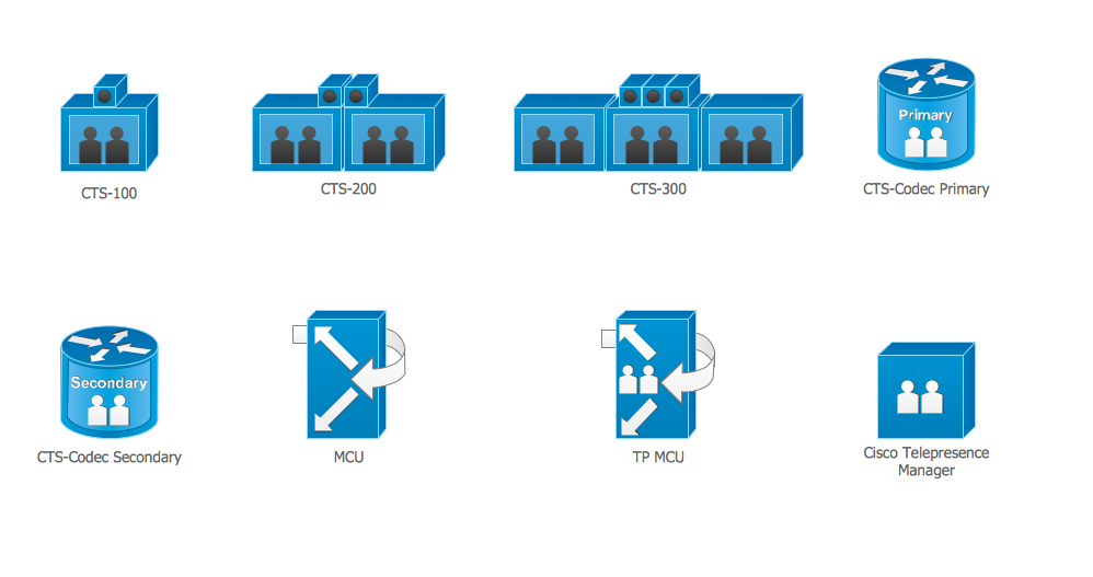
Cisco Telepresence. Cisco icons, shapes, stencils and symbols
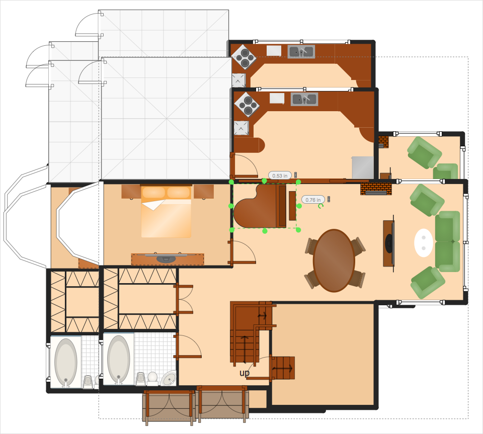
The vector stencils library "Dimensioning" contains 18 dimensions shapes.
Use it to create your landscape design and garden plans.
"Geometric dimensioning and tolerancing (GD&T) is a system for defining and communicating engineering tolerances. It uses a symbolic language on engineering drawings and computer-generated three-dimensional solid models that explicitly describes nominal geometry and its allowable variation. It tells the manufacturing staff and machines what degree of accuracy and precision is needed on each controlled feature of the part. GD&T is used to define the nominal (theoretically perfect) geometry of parts and assemblies, to define the allowable variation in form and possible size of individual features, and to define the allowable variation between features.
Dimensioning specifications define the nominal, as-modeled or as-intended geometry. One example is a basic dimension." [Geometric dimensioning and tolerancing. Wikipedia]
The dimensions shapes example "Design elements - Dimensioning" was created using the ConceptDraw PRO diagramming and vector drawing software extended with the Landscape & Garden solution from the Building Plans area of ConceptDraw Solution Park.
Dimension shapes

ER Diagram Styles

Cisco Security. Cisco icons, shapes, stencils and symbols

HelpDesk
How to Resize Objects
- How to Draw Geometric Shapes in ConceptDraw PRO ...
- Sketch The Following Geometrical Shapes Pyramid Prismand Cone
- Design elements - Solid geometry | How to Draw Geometric Shapes ...
- How to Draw Geometric Shapes in ConceptDraw PRO | Design ...
- How to Draw Geometric Shapes in ConceptDraw PRO | Beautiful ...
- How to Draw Geometric Shapes in ConceptDraw PRO ...
- How to Draw Geometric Shapes in ConceptDraw PRO ...
- How to Draw Geometric Shapes in ConceptDraw PRO | Scientific ...
- Design elements - Cloud shapes | How to Draw Geometric Shapes ...
- How to Draw Geometric Shapes in ConceptDraw PRO ...