Network Topologies


Network Topologies
UML State Machine Diagram.Design Elements

Basic Flowchart Symbols and Meaning


Software Diagram Examples and Templates

State Machine Diagram


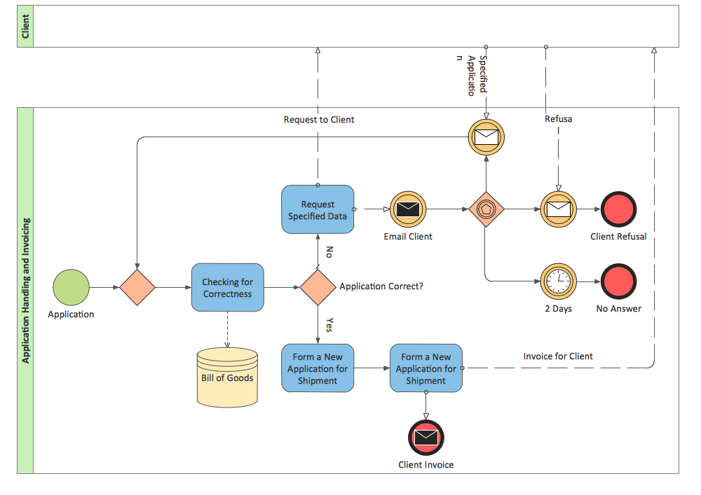
BPMN 2.0
Diagramming Software for Design UML State Machine Diagrams

"State machine diagram is a behavior diagram which shows discrete behavior of a part of designed system through finite state transitions. State machine diagrams can also be used to express the usage protocol of part of a system. Two kinds of state machines defined in UML 2.4 are:
(1) behavioral state machine, and
(2) protocol state machine.
The following nodes and edges are typically drawn in state machine diagram: behavioral state, behavioral transition, protocol state, protocol transition, different pseudostates. ...
Behavioral state machine is specialization of behavior and is used to specify discrete behavior of a part of designed system through finite state transitions. The state machine formalism used in this case is an object-based variant of Harel statecharts.
Behavior is modeled as a traversal of a graph of state nodes connected with transitions. Transitions are triggered by the dispatching of series of events. During the traversal, the state machine could also execute some activities. ...
Protocol state machine is a specialization of behavioral state machine and is used to express usage protocol or lifecycle of a classifier. It specifies which operations of the classifier can be called in which state and under which condition, thus specifying the allowed call sequences on the classifier’s operations. Protocol state machines express the legal transitions that a classifier can trigger." [uml-diagrams.org/ state-machine-diagrams.html]
The template "UML state machine diagram" for the ConceptDraw PRO diagramming and vector drawing software is included in the Rapid UML solution from the Software Development area of ConceptDraw Solution Park.
www.conceptdraw.com/ solution-park/ software-uml
UML state machine diagram

UML Diagram Types List

- Office pictograms - Vector stencils library | Fax Machine Diagram In ...
- Fax Machine Computer Diagram
- How To Draw Fax Machine
- Network Topologies | Computer Network Diagrams | Cisco Network ...
- Fax Pictogram
- ConceptDraw PRO ER Diagram Tool | Flow Diagram | Technical ...
- Design elements - Office equipment | How To Draw Building Plans ...
- State Machine Diagram | Building Drawing Software for Design ...
- Computer Network Diagrams | With The Aid Of Diagram Describe ...