Flow Chart Design — How to Design a Good Flowchart

Ordering Process Flowchart. Flowchart Examples

Basic of Flowchart: Meaning and Symbols


Account FlowchartFlowchart Examples

"In elementary algebra, a quadratic equation (from the Latin quadratus for "square") is any equation having the form
ax^2+bx+c=0
where x represents an unknown, and a, b, and c are constants with a not equal to 0. If a = 0, then the equation is linear, not quadratic. The constants a, b, and c are called, respectively, the quadratic coefficient, the linear coefficient and the constant or free term.
Because the quadratic equation involves only one unknown, it is called "univariate". The quadratic equation only contains powers of x that are non-negative integers, and therefore it is a polynomial equation, and in particular it is a second degree polynomial equation since the greatest power is two.
Quadratic equations can be solved by a process known in American English as factoring and in other varieties of English as factorising, by completing the square, by using the quadratic formula, or by graphing." [Quadratic equation. Wikipedia]
The flowchart example "Solving quadratic equation algorithm" was created using the ConceptDraw PRO diagramming and vector drawing software extended with the Mathematics solution from the Science and Education area of ConceptDraw Solution Park.
Solving quadratic equation flow chart

Flowchart Components

 Healthcare Management Workflow Diagrams
Healthcare Management Workflow Diagrams solution contains large set of colorful samples and libraries with predesigned vector pictograms and symbols of health, healthcare equipment, medical instruments, pharmaceutical tools, transport, medication, departments of healthcare organizations, the medical icons of people and human anatomy, flowchart objects, connectors, and arrows, which make it the best for designing clear and comprehensive Medical Workflow Diagrams and Block Diagrams, Healthcare Management Flowcharts and Infographics, Healthcare Workflow Diagram, for depicting the healthcare workflow and clinical workflows in healthcare, for making the workflow analysis healthcare and healthcare workflow management.
Examples of Flowcharts, Org Charts and More


Types of Flowcharts


Basic Diagramming


Basic Diagramming Flowchart Software

Chart Examples

Personal area (PAN) networks. Computer and Network Examples
 networks")

Social Media Flowchart Symbols

Basic Diagramming


Types of Flowchart — Overview

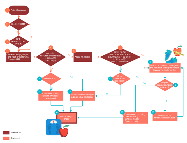
This medical flowchart sample shows assessment and treatment algorithm for overweight and obesity.
It was drawn on the base of Wikimedia Commons file: Assessment and treatment algorithm for overweight and obesity.png. [commons.wikimedia.org/ wiki/ File:Assessment_ and_ treatment_ algorithm_ for_ overweight_ and_ obesity.png]
"A medical algorithm is any computation, formula, statistical survey, nomogram, or look-up table, useful in healthcare. Medical algorithms include decision tree approaches to healthcare treatment (e.g., if symptoms A, B, and C are evident, then use treatment X) and also less clear-cut tools aimed at reducing or defining uncertainty." [Medical algorithm. Wikipedia]
The medical flow chart example "Assessment and treatment algorithm for overweight and obesity" was designed using ConceptDraw PRO software extended with Healthcare Workflow Diagrams solution from Business Processes area of ConceptDraw Solution Park.
Medical flowchart
Flow Diagram Software

Material Requisition Flowchart. Flowchart Examples

- Solving quadratic equation algorithm - Flowchart | Euclidean ...
- Euclidean algorithm - Flowchart | Solving quadratic equation ...
- Flowchart | By Using Algorithms C Solve Quadratic Equation Examples
- How To Write Algorithm And Flowchart For C Programs Involving Fns
- C Algorthm Introduction Flowchart Wikipidia
- Solving quadratic equation algorithm - Flowchart | Software ...
- Solving quadratic equation algorithm - Flowchart | Chemistry ...
- Contoh Flowchart | Flowchart Of Sorting In C
- How to Remove ConceptDraw Products from Mac and PC ...
- Flow Chart For How To Swim In C