Percentage Pie Chart. Pie Chart Examples

Pie Chart Examples and Templates

HVAC Business Plan

 HVAC Plans
Use HVAC Plans solution to create professional, clear and vivid HVAC-systems design plans, which represent effectively your HVAC marketing plan ideas, develop plans for modern ventilation units, central air heaters, to display the refrigeration systems for automated buildings control, environmental control, and energy systems.
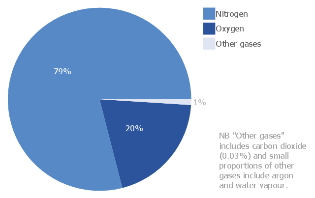
This pie chart sample shows the atmosphere air composition. It was designed on the base of the Wikimedia Commons file: Air composition pie chart.JPG.
[commons.wikimedia.org/ wiki/ File:Air_ composition_ pie_ chart.JPG]
This file is licensed under the Creative Commons Attribution-Share Alike 3.0 Unported license. [creativecommons.org/ licenses/ by-sa/ 3.0/ deed.en]
"The atmosphere of Earth is a layer of gases surrounding the planet Earth that is retained by Earth's gravity. The atmosphere protects life on Earth by absorbing ultraviolet solar radiation, warming the surface through heat retention (greenhouse effect), and reducing temperature extremes between day and night (the diurnal temperature variation).
The common name given to the atmospheric gases used in breathing and photosynthesis is air. By volume, dry air contains 78.09% nitrogen, 20.95% oxygen, 0.93% argon, 0.039% carbon dioxide, and small amounts of other gases. Air also contains a variable amount of water vapor, on average around 1%. Although air content and atmospheric pressure vary at different layers, air suitable for the survival of terrestrial plants and terrestrial animals currently is only known to be found in Earth's troposphere and artificial atmospheres." [Atmosphere of Earth. Wikipedia]
The pie chart example "Atmosphere air composition" was created using the ConceptDraw PRO diagramming and vector drawing software extended with the Pie Charts solution of the Graphs and Charts area in ConceptDraw Solution Park.
Pie chart
This HVAC schematics sample depicts the house cool mode of central air pool heater. It was drawn on the base of the HVAC schematics in the post "Central Air Pool Heater" from the Nathan Stratton's blog.
"With House Cool Mode, hot gas leaves the compressor runs through the reversing value into the condenser where it condenses into a liquid. Valve #1 is ON so liquid is able to leave the outside unit and run through the filter dryer and site glass into the evaporator upstairs in the house where the liquid flashes into a gas as it passes through the expansion valve and absorbs heat from the air passing through the evaporator. The cold gas travels downstairs and outside to the compressor and the cycle starts all over again." [robotics.net/ projects/ central-air-pool-heater/ ]
The HVAC schematics example "Central air pool heater" was created using the ConceptDraw PRO diagramming and vector drawing software extended with the HVAC Plans solution from the Building Plans area of ConceptDraw Solution Park.
HVAC schematics

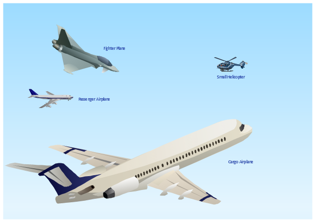
Use vector clipart library Aircraft to illustrate your documents, infographics, presentations and websites with images of aerial vehicles using ConceptDraw PRO diagramming and vector drawing software.
"An aircraft is a machine that is able to fly by gaining support from the air, or, in general, the atmosphere of a planet. It counters the force of gravity by using either static lift or by using the dynamic lift of an airfoil, or in a few cases the downward thrust from jet engines.
The human activity that surrounds aircraft is called aviation. Crewed aircraft are flown by an onboard pilot, but unmanned aerial vehicles may be remotely controlled or self-controlled by onboard computers." [Aircraft. Wikipedia]
The vector stencils library Aircraft is included in the Aerospace and Transport solution from Illustration area of ConceptDraw Solution Park.
Vector illustration
This HVAC plan sample shows the air handler layout on the floor plan.
"An air handler, or air handling unit (often abbreviated to AHU), is a device used to condition and circulate air as part of a heating, ventilating, and air-conditioning (HVAC) system. An air handler is usually a large metal box containing a blower, heating or cooling elements, filter racks or chambers, sound attenuators, and dampers. Air handlers usually connect to a ductwork ventilation system that distributes the conditioned air through the building and returns it to the AHU. Sometimes AHUs discharge (supply) and admit (return) air directly to and from the space served without ductwork.
Small air handlers, for local use, are called terminal units, and may only include an air filter, coil, and blower; these simple terminal units are called blower coils or fan coil units. A larger air handler that conditions 100% outside air, and no recirculated air, is known as a makeup air unit (MAU). An air handler designed for outdoor use, typically on roofs, is known as a packaged unit (PU) or rooftop unit (RTU)." [Air handler. Wikipedia]
The floor plan example "Air handler - HVAC plan" was created using the ConceptDraw PRO diagramming and vector drawing software extended with the HVAC Plans solution from the Building Plans area of ConceptDraw Solution Park.
Floor plan

Business Report Pie. Pie Chart Examples

Pie Donut Chart. Pie Chart Examples

Pie Graph Worksheets

This HVAC floor plan sample shows the ventilation duct system layout.
"Ducts are used in heating, ventilation, and air conditioning (HVAC) to deliver and remove air. The needed airflows include, for example, supply air, return air, and exhaust air. Ducts commonly also deliver ventilation air as part of the supply air. As such, air ducts are one method of ensuring acceptable indoor air quality as well as thermal comfort.
A duct system is also called ductwork. Planning (laying out), sizing, optimizing, detailing, and finding the pressure losses through a duct system is called duct design." [Duct (flow). Wikipedia]
The HVAC floor plan example "Ductwork layout" was created using the ConceptDraw PRO diagramming and vector drawing software extended with the HVAC Plans solution from the Building Plans area of ConceptDraw Solution Park.
HVAC floor plan

The vector stencils library "HVAC ductwork" contains 55 ducts, vents and HVAC mechanical components symbols.
Use the design elements library "HVAC ductwork" for drawing the HVAC ductwork system diagrams, heating, ventilation, air conditioning, refrigeration, automated building control and environmental control system layout floor plans.
"Ducts are used in heating, ventilation, and air conditioning (HVAC) to deliver and remove air. These needed airflows include, for example, supply air, return air, and exhaust air. Ducts also deliver, most commonly as part of the supply air, ventilation air. As such, air ducts are one method of ensuring acceptable indoor air quality as well as thermal comfort.
A duct system is often called ductwork. Planning ('laying out'), sizing, optimizing, detailing, and finding the pressure losses through a duct system is called duct design." [Duct (HVAC). Wikipedia]
The shapes library "HVAC ductwork" is included in the HVAC Plans solution from the Building Plans area of ConceptDraw Solution Park.
HVAC ductwork symbols

HVAC Marketing Plan

The vector stencils library "Transmission paths" contains 43 symbols of power transmission paths, electronic circuits, bus connectors and elbows, terminals, junctions, and concentrators.
Use it to annotate electrical diagrams, electronic schematics and circuit diagrams.
"A physical medium in data communications is the transmission path over which a signal propagates.
Many transmission media are used as communications channel.
For telecommunications purposes in the United States, Federal Standard 1037C, transmission media are classified as one of the following:
(1) Guided (or bounded) - waves are guided along a solid medium such as a transmission line.
(2) Wireless (or unguided) - transmission and reception are achieved by means of an antenna.
One of the most common physical medias used in networking is copper wire. Copper wire to carry signals to long distances using relatively low amounts of power. The unshielded twisted pair (UTP) is eight strands of copper wire, organized into four pairs.
Another example of a physical medium is optical fiber, which has emerged as the most commonly used transmission medium for long-distance communications. Optical fiber is a thin strand of glass that guides light along its length.
Multimode and single mode are two types of commonly used optical fiber. Multimode fiber uses LEDs as the light source and can carry signals over shorter distances, about 2 kilometers. Single mode can carry signals over distances of tens of miles.
Wireless media may carry surface waves or skywaves, either longitudinally or transversely, and are so classified.
In both communications, communication is in the form of electromagnetic waves. With guided transmission media, the waves are guided along a physical path; examples of guided media include phone lines, twisted pair cables, coaxial cables, and optical fibers. Unguided transmission media are methods that allow the transmission of data without the use of physical means to define the path it takes. Examples of this include microwave, radio or infrared. Unguided media provide a means for transmitting electromagnetic waves but do not guide them; examples are propagation through air, vacuum and seawater.
The term direct link is used to refer to the transmission path between two devices in which signals propagate directly from transmitters to receivers with no intermediate devices, other than amplifiers or repeaters used to increase signal strength. This term can apply to both guided and unguided media.
A transmission may be simplex, half-duplex, or full-duplex.
In simplex transmission, signals are transmitted in only one direction; one station is a transmitter and the other is the receiver. In the half-duplex operation, both stations may transmit, but only one at a time. In full duplex operation, both stations may transmit simultaneously. In the latter case, the medium is carrying signals in both directions at same time." [Transmission medium. Wikipedia]
The shapes example "Design elements - Transmission paths" was drawn using the ConceptDraw PRO diagramming and vector drawing software extended with the Electrical Engineering solution from the Engineering area of ConceptDraw Solution Park.
Transmission path symbols

- Example Of Air Transportation
- Aircraft examples | Design elements - Aircraft | Transport - Template ...
- Percentage Pie Chart. Pie Chart Examples | Atmosphere air ...
- Five Examples Of Air Transport
- Atmosphere air composition | Pie Chart Examples and Templates ...
- Atmosphere air composition | Percentage Pie Chart. Pie Chart ...
- Draw The Example Of Air Transportation
- Air Transport Vehicles Pictures
- Design elements - Aircraft | Aircraft examples | Air Transport ...
- Examples Of Transport On Air
- Atmosphere air composition | Percentage Pie Chart. Pie Chart ...
- Pie Chart Examples and Templates | Aircraft examples | Percentage ...
- Atmosphere air composition | Percentage Pie Chart. Pie Chart ...
- Sales Process Flowchart. Flowchart Examples | Fresh Air Handling ...
- Security system plan | Fire Exit Plan. Building Plan Examples | Air ...
- Atmosphere air composition | Pie Chart Examples and Templates ...
- Atmosphere air composition | Swim Lane Diagrams | Percentage Pie ...
- Atmosphere air composition | Water cycle diagram | Percentage Pie ...
- HVAC Plans