Entity Relationship Diagram Examples


ERD Symbols and Meanings

UML Class Diagram Notation

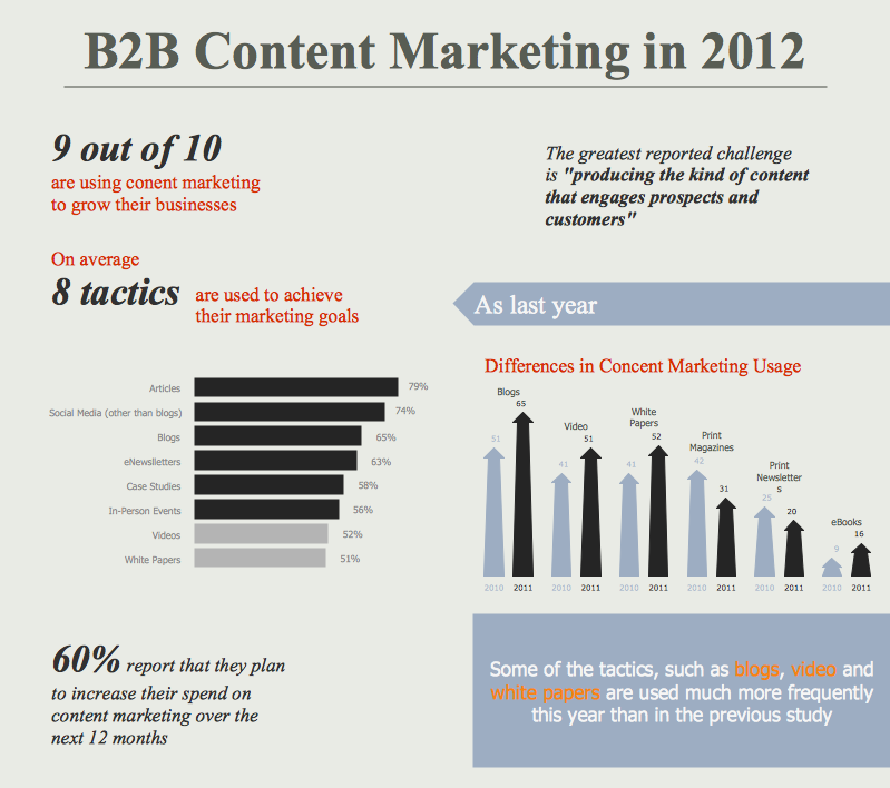
Content Marketing Infographics
UML Use Case Diagram Example. Social Networking Sites Project

Data structure diagram with ConceptDraw DIAGRAM

Business Process Mapping — How to Map a Work Process

Flowchart Components

Express-G Diagram
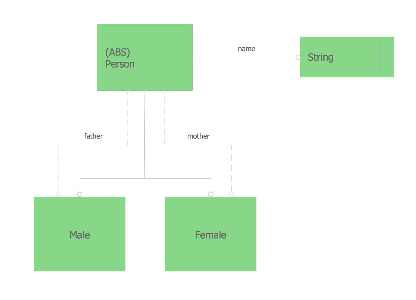
UML Class Diagram Generalization Example UML Diagrams

- Er Diagram Questions With Solutions Pdf
- Erd Questions And Answers
- Entity-Relationship Diagram ( ERD ) | Divided Bar Diagrams ...
- Questions On Entity Relationship Diagram With Answers
- Enhanced Er Diagram Questions And Answer Pdf
- Er Diagrams Questions And Answers Pdf
- Er Model Diagram Questions And Answers Pdf Free Download
- Entity-Relationship Diagram ( ERD ) | Question And Answer On ...
- Database Erd Question And Answers Pdf
- Extended Er Diagram Examples With Answers