ER Diagram for Cloud Computing

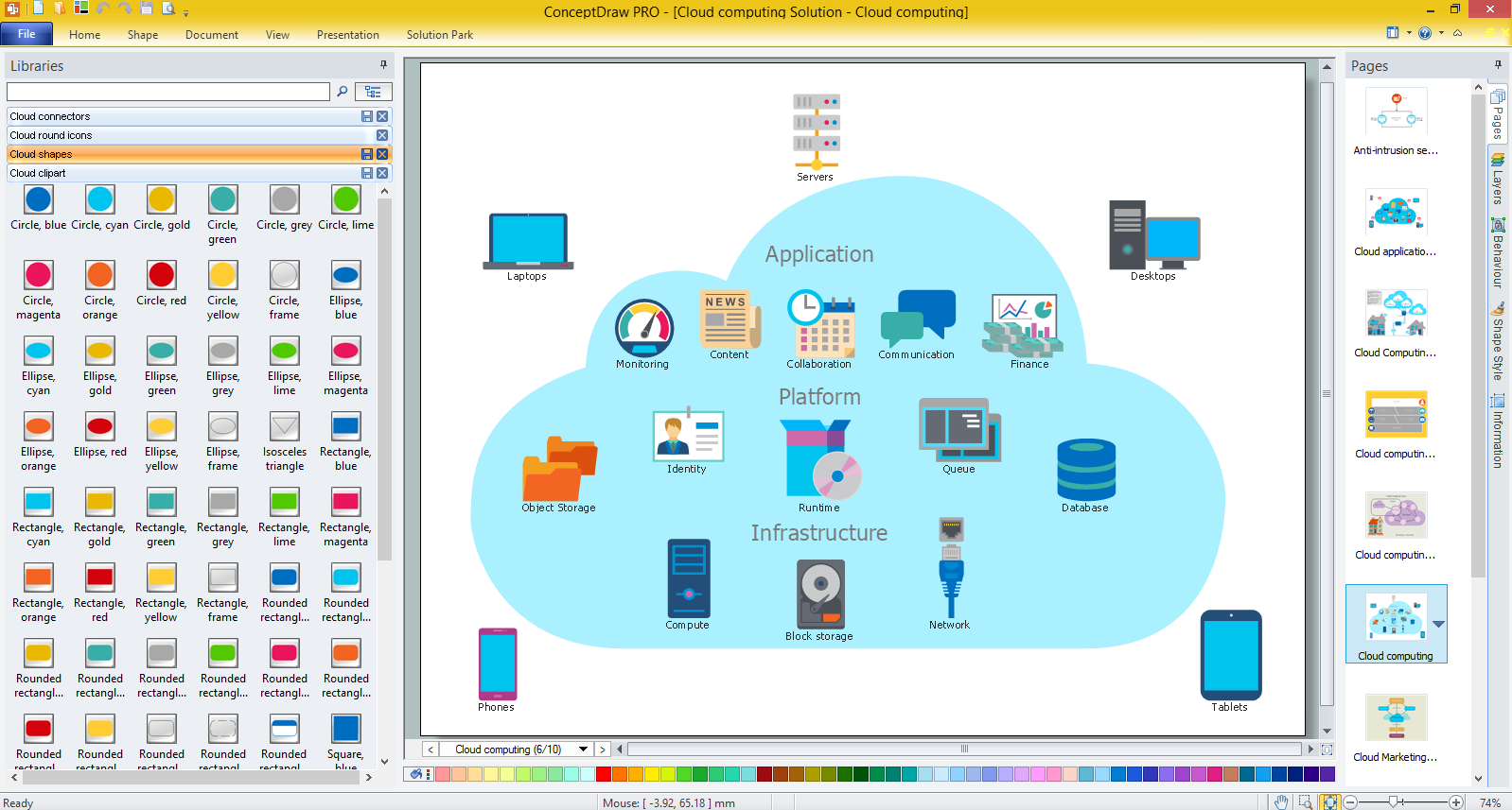
Cloud Computing

Introduction to Cloud Computing Architecture
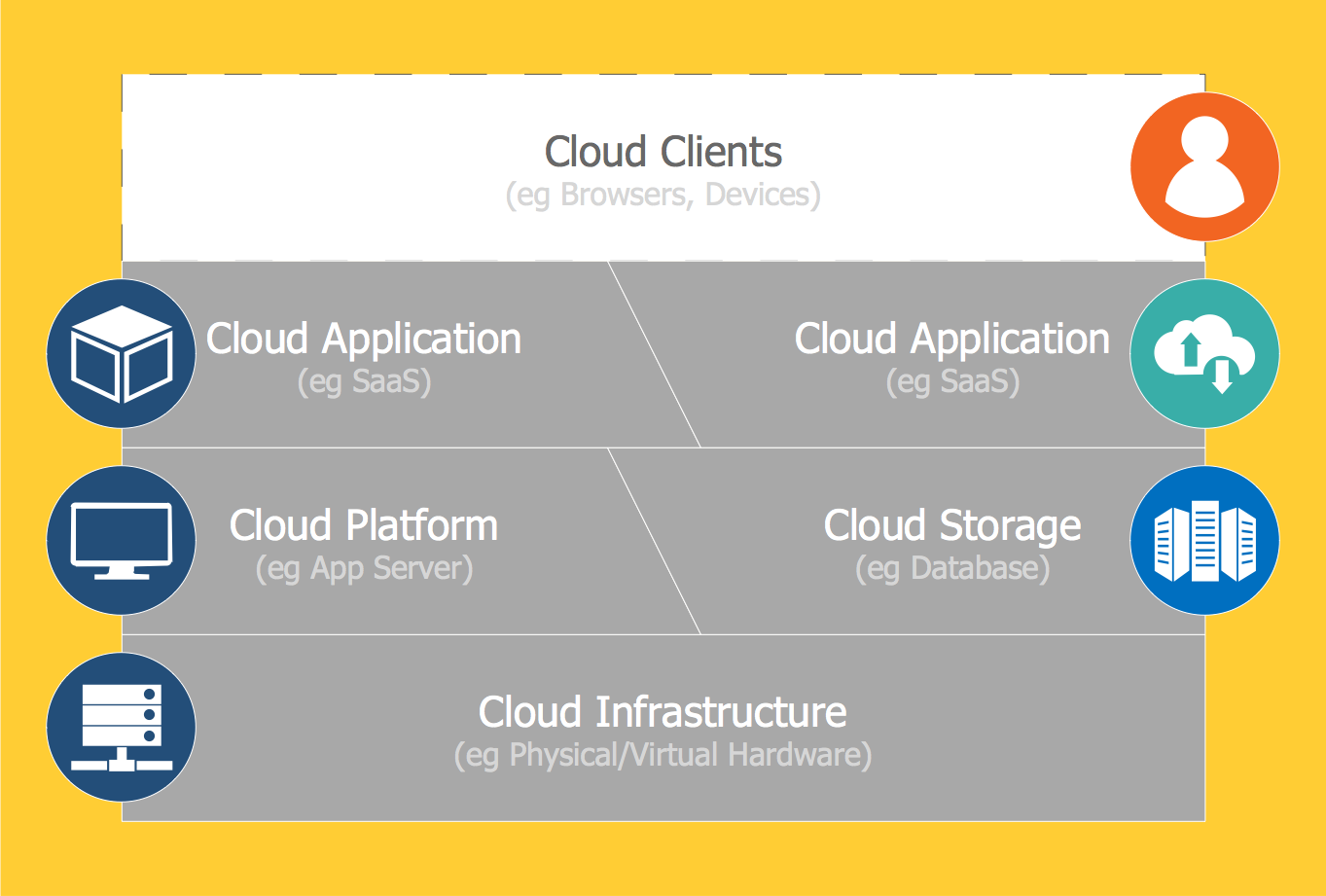
What is Cloud Computing
 Entity-Relationship Diagram (ERD)
An Entity-Relationship Diagram (ERD) is a visual presentation of entities and relationships. That type of diagrams is often used in the semi-structured or unstructured data in databases and information systems. At first glance ERD is similar to a flowch
Cisco Security. Cisco icons, shapes, stencils and symbols

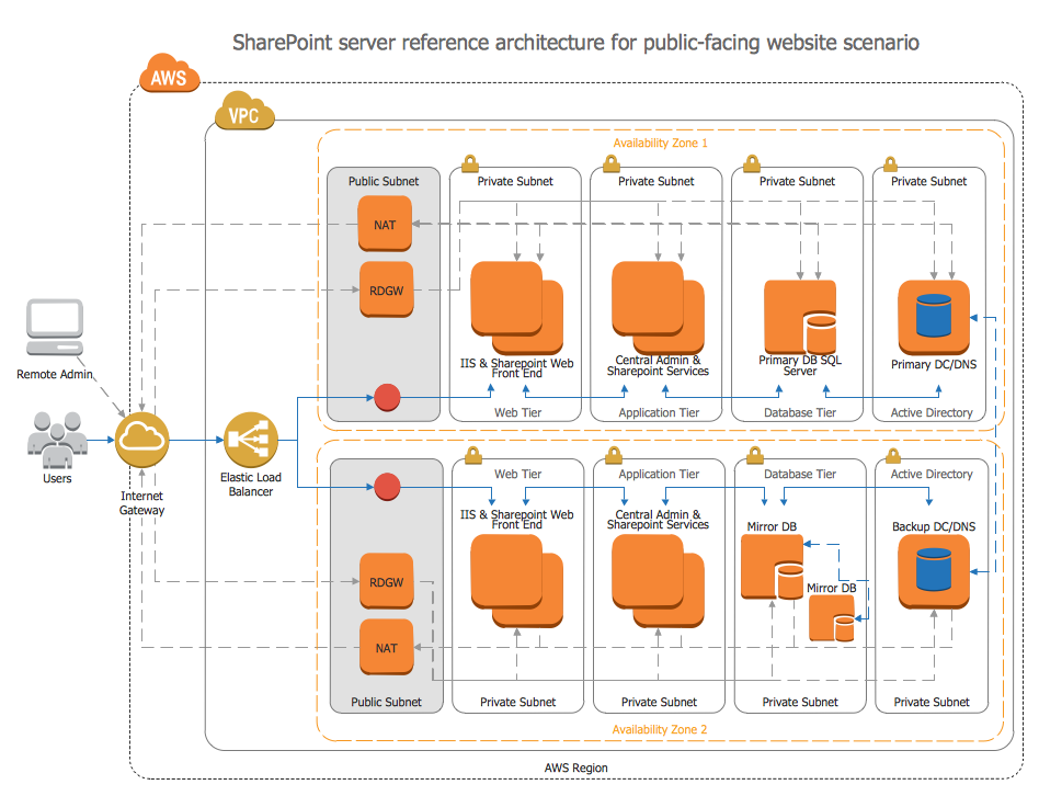
Amazon Web Services
ERD Symbols and Meanings


Entity Relationship Diagram Symbols

ConceptDraw DIAGRAM Network Diagram Tool


- ER Diagram for Cloud Computing | Cloud Computing Architecture ...
- ER Diagram In Cloud Storage Auditing
- Entity - Relationship Diagram (ERD) | Cloud Storage Of E R Diagram
- ER Diagram for Cloud Computing | Home area networks (HAN ...
- ER Diagram for Cloud Computing | Create Organizational Chart ...
- ER Diagram for Cloud Computing | Amazon Web Services | Entity ...
- Cloud Computing Architecture Diagrams | Network Security ...
- ER Diagram for Cloud Computing | Cloud Computing | How to ...
- Introduction to Cloud Computing Architecture | ER Diagram for ...
- ER Diagram for Cloud Computing | Amazon Web Services | How To ...