 Entity-Relationship Diagram (ERD)
An Entity-Relationship Diagram (ERD) is a visual presentation of entities and relationships. That type of diagrams is often used in the semi-structured or unstructured data in databases and information systems. At first glance ERD is similar to a flowch
Developing Entity Relationship Diagrams

 Entity-Relationship Diagram (ERD)
Entity-Relationship Diagram (ERD) solution extends ConceptDraw DIAGRAM software with templates, samples and libraries of vector stencils from drawing the ER-diagrams by Chen's and crow’s foot notations.
Draw Network Diagram based on Templates and Examples


 ConceptDraw Solution Park
ConceptDraw Solution Park collects graphic extensions, examples and learning materials
Cafe Floor Plan. Cafe Floor Plan Examples

Planogram
 Organizational Charts
Organizational Charts solution extends ConceptDraw DIAGRAM software with samples, templates and library of vector stencils for drawing the org charts.
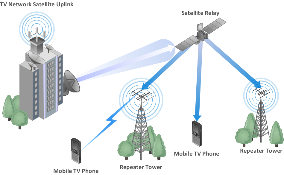
Wireless Network WAN
UML Class Diagram Example - Buildings and Rooms

 Computer Network Diagrams
Computer Network Diagrams solution extends ConceptDraw DIAGRAM software with samples, templates and libraries of vector icons and objects of computer network devices and network components to help you create professional-looking Computer Network Diagrams, to plan simple home networks and complex computer network configurations for large buildings, to represent their schemes in a comprehensible graphical view, to document computer networks configurations, to depict the interactions between network's components, the used protocols and topologies, to represent physical and logical network structures, to compare visually different topologies and to depict their combinations, to represent in details the network structure with help of schemes, to study and analyze the network configurations, to communicate effectively to engineers, stakeholders and end-users, to track network working and troubleshoot, if necessary.
UML Use Case Diagram Example. Social Networking Sites Project

- Er Diagram Of A Cyber Cafe Database
- Erd Dfd Examples For Cyber Cafe
- Entity - Relationship Diagram (ERD) | Network Layout Floor Plans ...
- Entity - Relationship Diagram (ERD) | ConceptDraw Solution Park ...
- Network Layout Floor Plans | Entity - Relationship Diagram (ERD ...
- How To Draw A Cafeteria Entity Relationship Diagram
- Architectural Drawing Of A Cyber Cafe
- Floor Plan Of Cyber Cafe
- Entity - Relationship Diagram (ERD) | Network Layout Floor Plans ...
- Floor Plan Of A Cyber Cafe
- Cyber Cafe Business Plan
- Er Diagram For Computer Shop Database
- Entity Relationship Diagram Software for Mac | Developing Entity ...
- Entity - Relationship Diagram (ERD) | Developing Entity Relationship ...
- Entity Relationship Diagram Software for Mac | Jacobson Use Cases ...
- Entity Relationship Diagram Software for Mac | Jacobson Use Cases ...
- Entity - Relationship Diagram (ERD) | ConceptDraw PRO ER ...
- Componenet Diagram For Cyber Cafe
- Example Use Case Diagram For Internet Cafe
- Entity Relationship Diagram Software Engineering | Organization ...