Electrical Symbols, Electrical Diagram Symbols

The vector stencils library "Analog and digital logic" contains 40 element symbols of logic (threshold) gates, bistable current switches, current controllers, regulators, electrical generators, and amplifiers.
Use it for drawing the digital and analog functions in electronic circuit diagrams and electrical schematics.
"Analogue electronics (or analog in American English) are electronic systems with a continuously variable signal, in contrast to digital electronics where signals usually take only two different levels. The term "analogue" describes the proportional relationship between a signal and a voltage or current that represents the signal." [Analogue electronics. Wikipedia]
"Digital electronics, or digital (electronic) circuits, represent signals by discrete bands of analog levels, rather than by a continuous range. All levels within a band represent the same signal state. Relatively small changes to the analog signal levels due to manufacturing tolerance, signal attenuation or parasitic noise do not leave the discrete envelope, and as a result are ignored by signal state sensing circuitry.
In most cases the number of these states is two, and they are represented by two voltage bands: one near a reference value (typically termed as "ground" or zero volts) and a value near the supply voltage, corresponding to the "false" ("0") and "true" ("1") values of the Boolean domain respectively.
Digital techniques are useful because it is easier to get an electronic device to switch into one of a number of known states than to accurately reproduce a continuous range of values.
Digital electronic circuits are usually made from large assemblies of logic gates, simple electronic representations of Boolean logic functions." [Digital electronics. Wikipedia]
The example "Design elements - Analog and digital logic" was drawn using the ConceptDraw PRO diagramming and vector drawing software extended with the Electrical Engineering solution from the Engineering area of ConceptDraw Solution Park.
Analog and digital logic elements

Electrical Symbols — Resistors

HelpDesk
How to Draw an Electrical Scheme Using Electrical Engineering Solution

Electrical Symbols — Analog and Digital Logic

 Engineering
This solution extends ConceptDraw DIAGRAM.4 with the ability to visualize industrial systems in electronics, electrical, chemical, process, and mechanical engineering.
Electrical Symbols — Logic Gate Diagram

HR infographics "Electronic human resources (E-HR)" was redesigned from the Wikimedia Commons file: Ehr diagram.jpg. [commons.wikimedia.org/ wiki/ File:Ehr_ diagram.jpg]
This file is licensed under the Creative Commons Attribution-Share Alike 3.0 Unported license. [creativecommons.org/ licenses/ by-sa/ 3.0/ ]
"E-HR is a function of HR that is concerned with the use, management, and regulation of electronic information and processes within an organization.
E-HR is different from E-HRM (Electronic Human Resource Management) and HRIS (Human Resource Information System) which are uses of technology. More specifically, E-HRM is a system that allows management and employees access to human resource related information and services through an organization's intranet or web portal. HRIS refers to enterprise resource planning software that streamlines human resource functions such as payroll.
In contrast, E-HR is a function of human resources that requires cross-functional knowledge and collaboration between multiple departments, most notably human resources and information technology." [Electronic human resources. Wikipedia]
The HR infographics example "Electronic human resources (E-HR)" was created using the ConceptDraw PRO diagramming and vector drawing software extended with the HR Flowcharts solution from the Management area of ConceptDraw Solution Park.
HR infographics
.png--diagram-flowchart-example.png)
Used Solutions
Circuits and Logic Diagram Software

Electrical Symbols — Terminals and Connectors

Wiring Diagrams with ConceptDraw DIAGRAM

Electrical Symbols — Electrical Circuits

Electrical Design Software

Electrical Symbols — Integrated Circuit

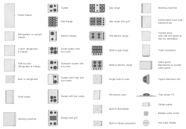
The vector stencils library Appliances contains 36 symbols of kitchen appliances, laundry appliances, stoves, cooking appliances, and laundry equipment.
Use the shapes library Appliances to draw equipment layouts and interior design floor plans of kitchens, laundry rooms, utility rooms using the ConceptDraw PRO diagramming and vector drawing software.
"Home appliances are electrical/ mechanical machines which accomplish some household functions, such as cooking or cleaning. Home appliances can be classified into:
Major appliances, or White goods;
Small appliances, or Brown goods;
Consumer electronics, or Shiny goods.
White goods/ major appliances comprise major household appliances and may include: air conditioner, dishwasher, clothes dryer, drying cabinet, freezer, refrigerator, kitchen stove, water heater, washing machine, trash compactor, microwave ovens and induction cookers.
Brown goods/ small appliances are typically small household electrical entertainment appliances such as: TV sets, CD and DVD players, camcorders, still cameras, clocks, alarm clocks, video game consoles, HiFi and home cinema, telephones and answering machines.
Consumer electronics (abbreviated CE) are electronic equipment intended for everyday use, most often in entertainment, communications and office productivity. Main products include radio receivers, television sets, MP3 players, video recorders, DVD players, digital cameras, camcorders, personal computers, video game consoles, telephones and mobile phones." [Home appliance. Wikipedia]
The design elements library Appliances is provided by the Floor Plans solution from the Building Plans area of ConceptDraw Solution Park.
- Block Diagram Electronics Draw
- Electronics With Technical Drawing
- Engineering Electronics Graphics Pdf
- Electronics Components Symbol And Functions With Physical
- Digital Electronic Symbols
- Example Drawing In Electronics Engineering
- Electronic Components Symbols And Functions Pdf
- Electronics Engineering System Design Diagrams
- Electronics Mechinic Block Diagram Pdf
- All Electronics Ckt Element
- Electronics Symble
- Symbol Electronics
- Electronics Block Diagrams And Symbols Pdf
- Electronics Engineers Png Vector
- Electronics Block Diagram Software
- Electronics Engineering Drawing
- Design elements - Thermo | Temp Probe Symbol Electronics
- Digital Electronics
- Electronics Components Block Diagram Pdf