Electrical Symbols — Integrated Circuit

Electrical Symbols, Electrical Diagram Symbols

Network Diagram Software. LAN Network Diagrams. Physical Office Network Diagrams


Interior Design. Piping Plan — Design Elements

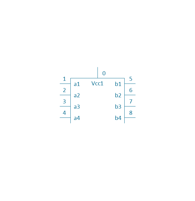
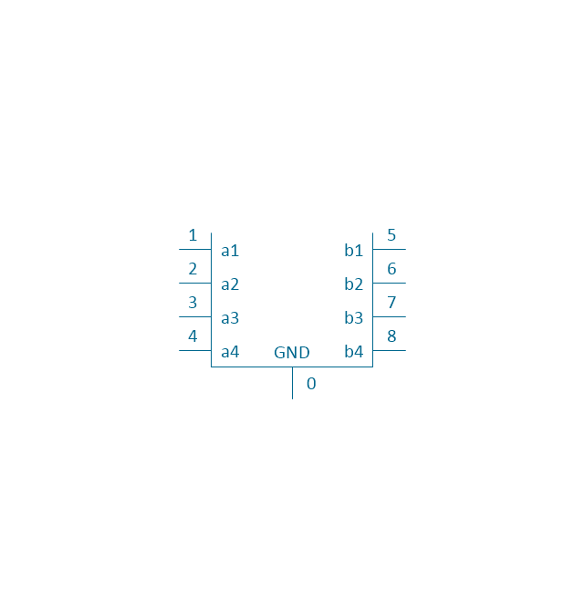
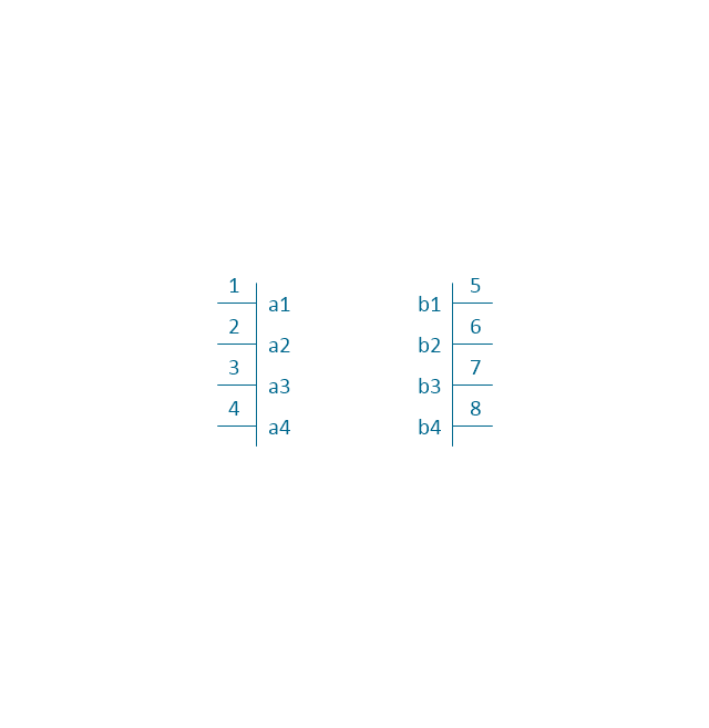
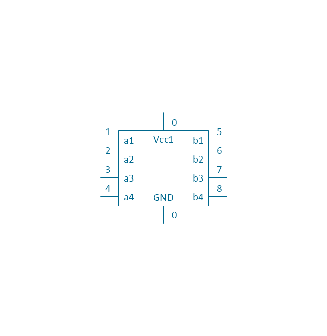
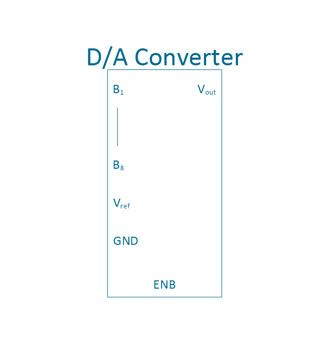
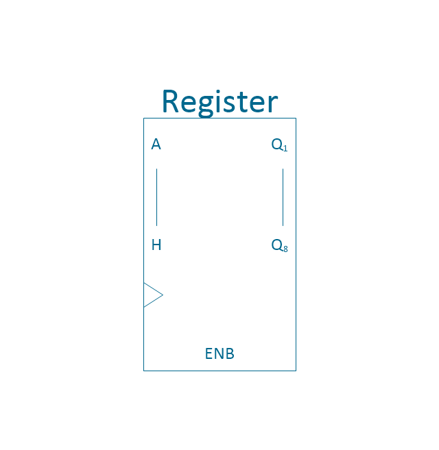
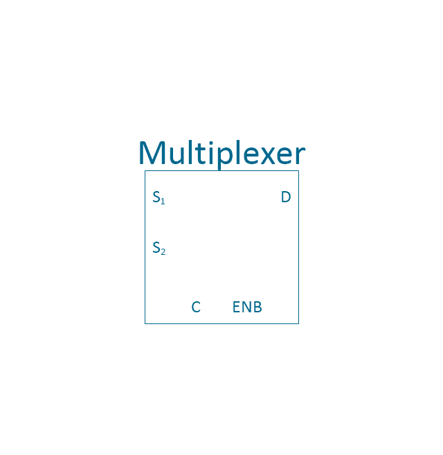
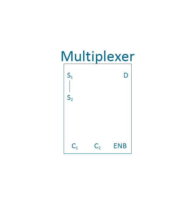
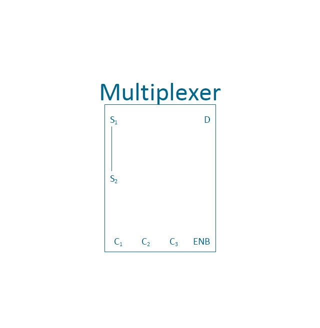
The vector stencils library "Integrated circuit" contains 43 components of integrated circuits.
Use these shapes for integrated circuit design, including transducers, rotary devices, converters, registers, analog switches, counters, registers, decoders, and multiplex transmitters in the ConceptDraw PRO diagramming and vector drawing software extended with the Electrical Engineering solution from the Engineering area of ConceptDraw Solution Park.
www.conceptdraw.com/ solution-park/ engineering-electrical
4X top block
4X base block
Board

4X middle block
4X complete block
1X top block
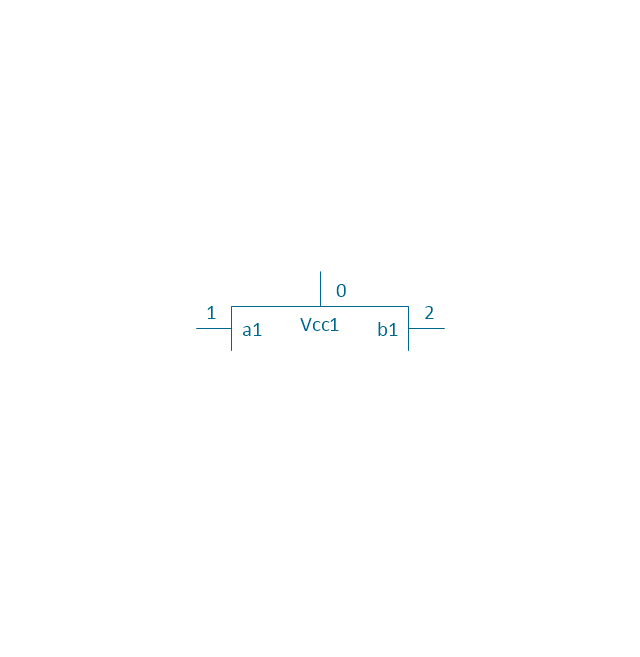
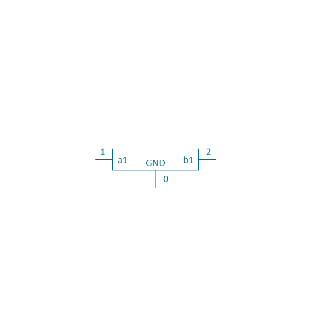
1X base block
1X middle block

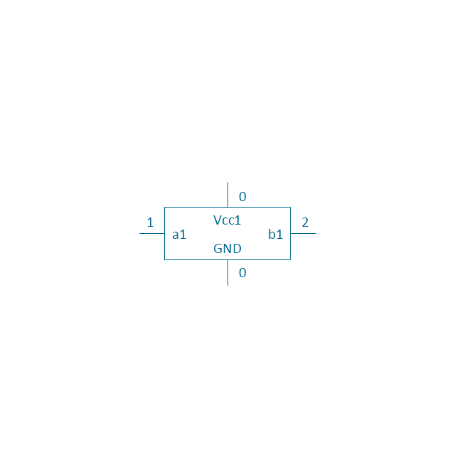
1X complete block
Negative logic dot

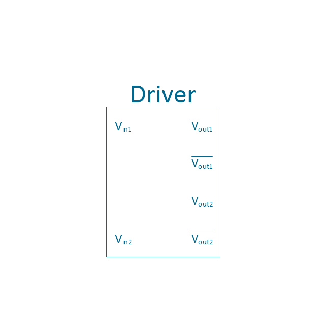
Driver
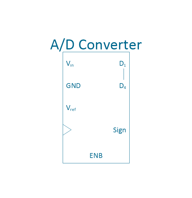
4-bit a/d converter
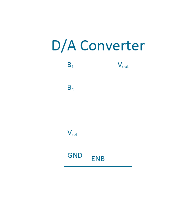
4-bit d/a converter
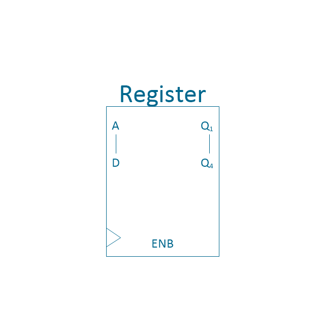
4-bit register
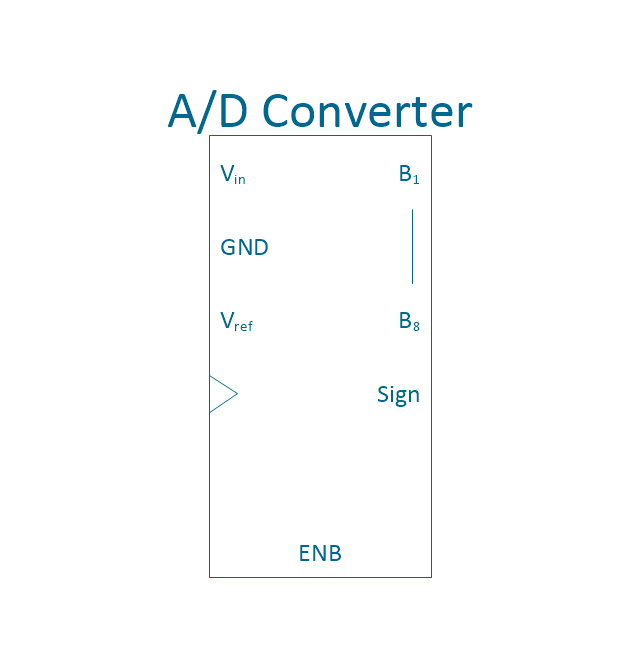
8-bit a/d converter
8-bit d/a converter
8-bit register
MUX 2
MUX 4
MUX 8
4-bit counter
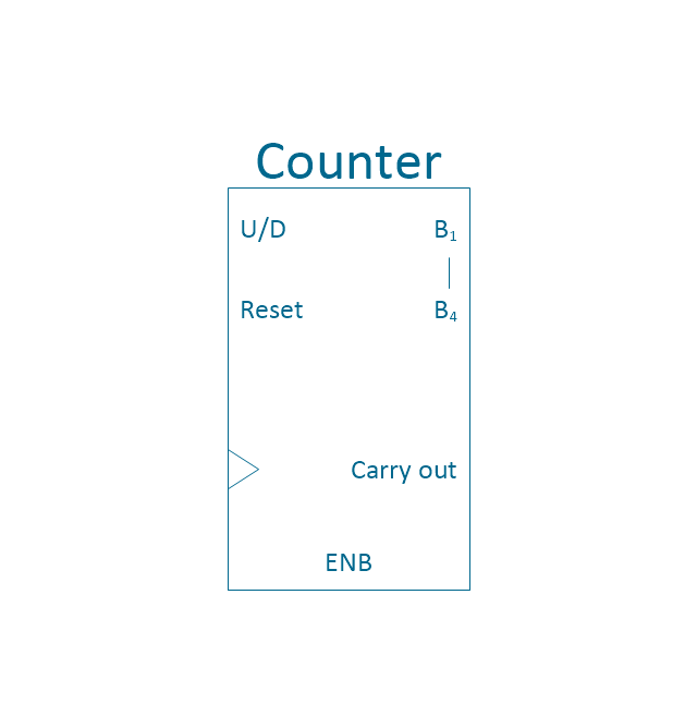
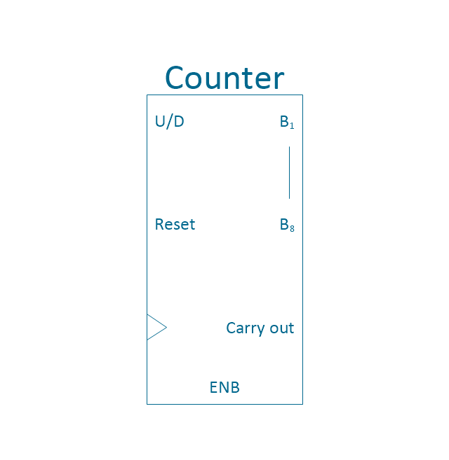
Counter
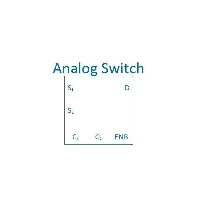
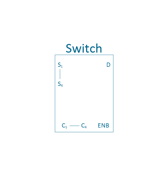
Analog switch 2
Preload counter 4
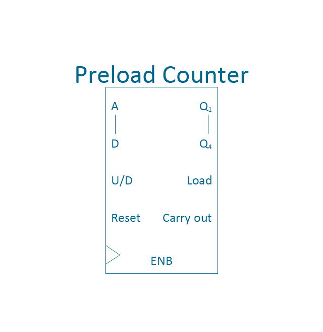
Preload Counter
Analog switch 4
2 - 4 decoder
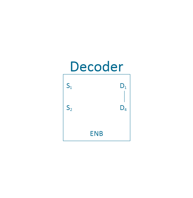
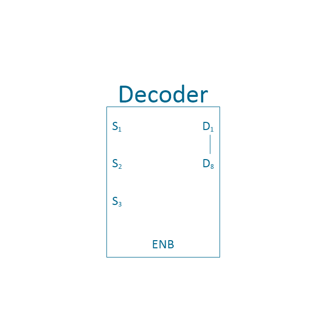
3 - 8 decoder
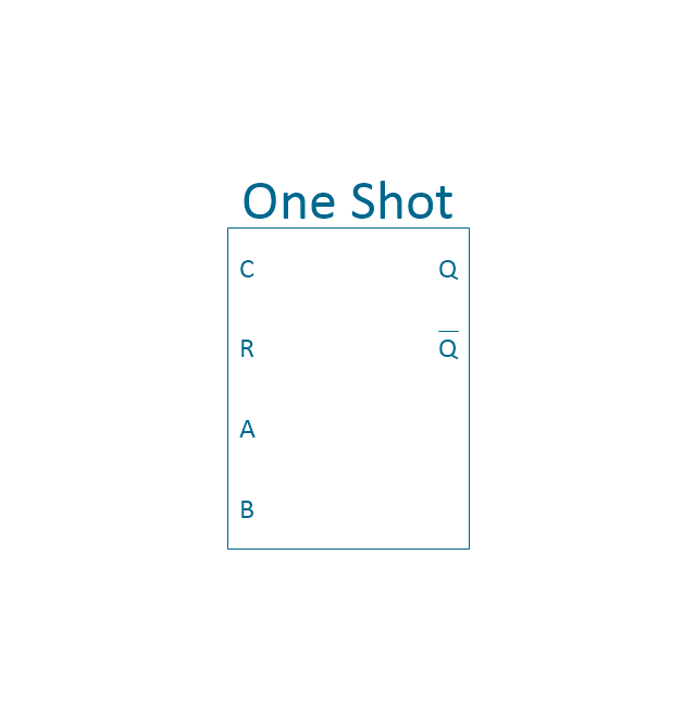
One shot
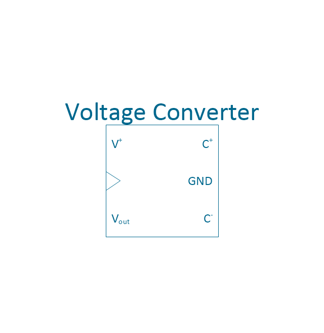
Voltage converter
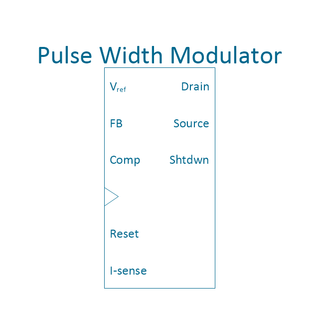
PWM
Horizontal extension

Horizontal extension 2

Horizontal extension, overline

Horizontal extension, overline 2

Vertical extension

Vertical extension 2

Vertical extension, overline

Vertical extension, overline 2

Switch point

Switch point 2

Ground

Ground 2

 IDEF Business Process Diagrams
Use the IDEF Business Process Diagrams solution to create effective database designs and object-oriented designs, following the integration definition methodology.
Basic Flowchart Symbols and Meaning


 Scrum Workflow
The Scrum Workflow Solution extends the capabilities of ConceptDraw DIAGRAM with a large collection of professionally-designed samples and a selection of ready-to-use scrum design elements: scrum diagrams and arrows, scrum icons of people, artifacts, workflow, workspace and other colorful scrum clipart, and also scrum charts.
The vector stencils library "Integrated circuit" contains 43 components of integrated circuits.
Use these shapes for integrated circuit design, including transducers, rotary devices, converters, registers, analog switches, counters, registers, decoders, and multiplex transmitters in the ConceptDraw PRO diagramming and vector drawing software extended with the Electrical Engineering solution from the Engineering area of ConceptDraw Solution Park.
www.conceptdraw.com/ solution-park/ engineering-electrical
Use these shapes for integrated circuit design, including transducers, rotary devices, converters, registers, analog switches, counters, registers, decoders, and multiplex transmitters in the ConceptDraw PRO diagramming and vector drawing software extended with the Electrical Engineering solution from the Engineering area of ConceptDraw Solution Park.
www.conceptdraw.com/ solution-park/ engineering-electrical
4X top block
4X base block
Board
4X middle block
4X complete block
1X top block
1X base block
1X middle block
1X complete block
Negative logic dot
Driver
4-bit a/d converter
4-bit d/a converter
4-bit register
8-bit a/d converter
8-bit d/a converter
8-bit register
MUX 2
MUX 4
MUX 8
4-bit counter
Counter
Analog switch 2
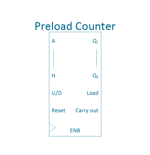
Preload counter 4
Preload Counter
Analog switch 4
2 - 4 decoder
3 - 8 decoder
One shot
Voltage converter
PWM
Horizontal extension
Horizontal extension 2
Horizontal extension, overline
Horizontal extension, overline 2
Vertical extension
Vertical extension 2
Vertical extension, overline
Vertical extension, overline 2
Switch point
Switch point 2
Ground
Ground 2
 SYSML
SYSML
The SysML solution helps to present diagrams using Systems Modeling Language; a perfect tool for system engineering.
- Circuit Diagram Of Rotating Extension Board
- Integrated circuit - Vector stencils library | Extension Board Drawing ...
- Electric Circuit Project Extension Board
- Electrical Symbols — Integrated Circuit | ConceptDraw Arrows10 ...
- Electrical Symbols, Electrical Diagram Symbols | Electrical Symbols ...
- Electric Extension Drawing
- How To Make Extension Board 3 Switch 2 Plug 1light Digaram
- How to Create an Electrical Diagram Using ConceptDraw PRO ...
- Electrical Symbols, Electrical Diagram Symbols | How To use House ...