Electrical Symbols, Electrical Diagram Symbols

Electrical Symbols — Electrical Circuits

The vector stencils library "Integrated circuit" contains 43 components of integrated circuits.
Use these shapes for integrated circuit design, including transducers, rotary devices, converters, registers, analog switches, counters, registers, decoders, and multiplex transmitters in the ConceptDraw PRO diagramming and vector drawing software extended with the Electrical Engineering solution from the Engineering area of ConceptDraw Solution Park.
www.conceptdraw.com/ solution-park/ engineering-electrical
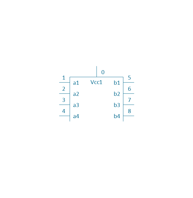
4X top block
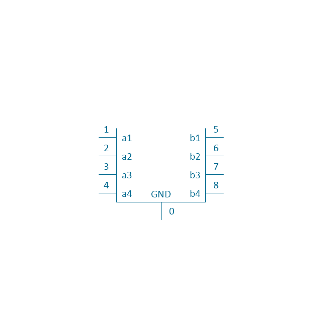
4X base block
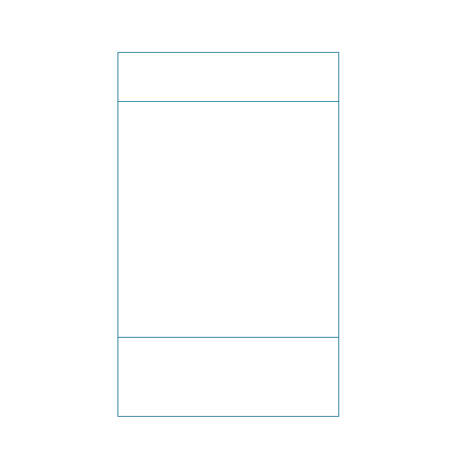
Board
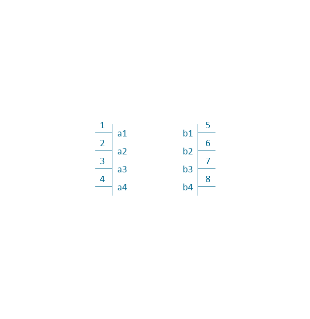
4X middle block
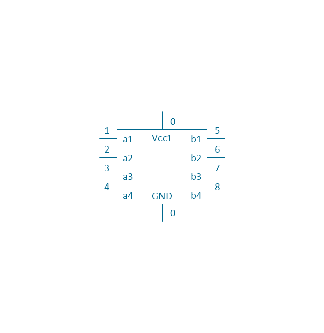
4X complete block
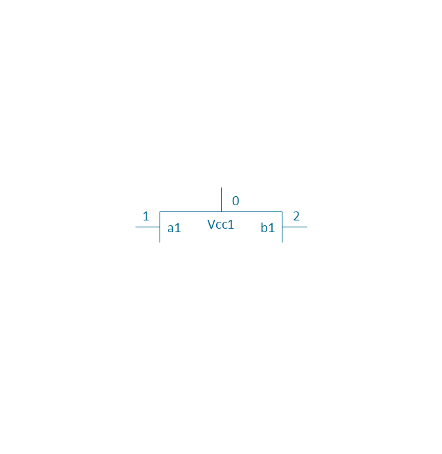
1X top block
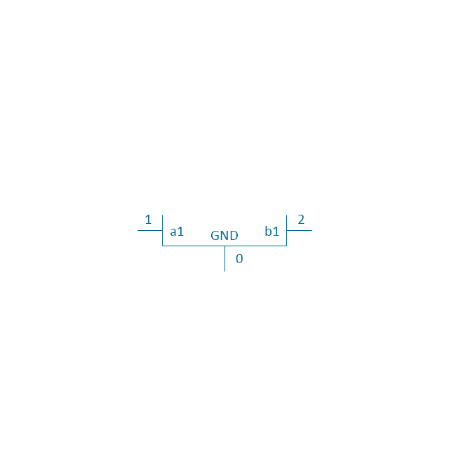
1X base block
1X middle block
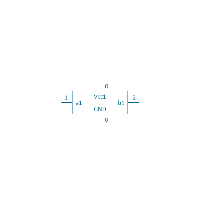
1X complete block
Negative logic dot

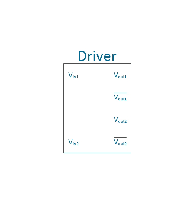
Driver
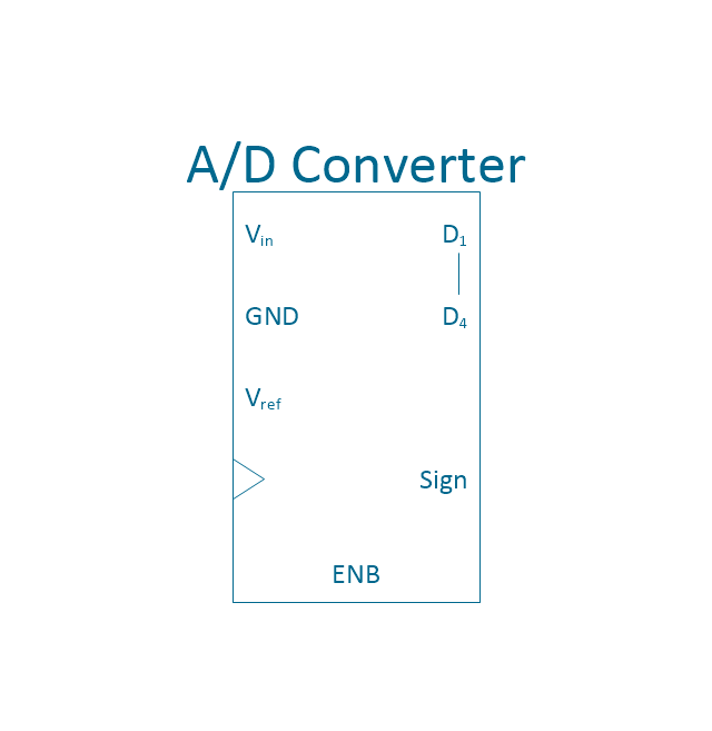
4-bit a/d converter
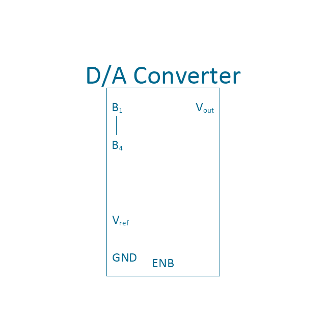
4-bit d/a converter
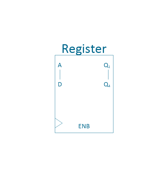
4-bit register
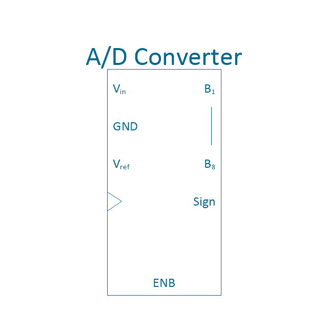
8-bit a/d converter
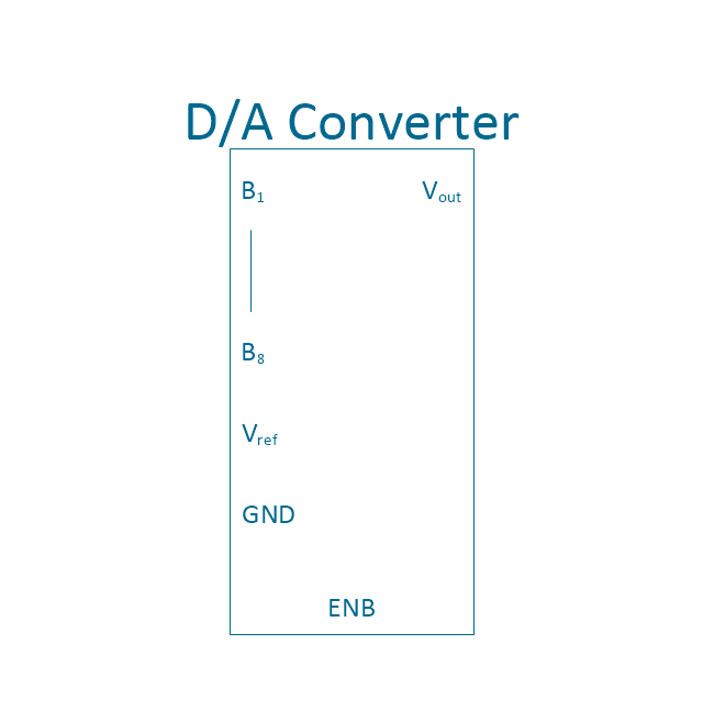
8-bit d/a converter
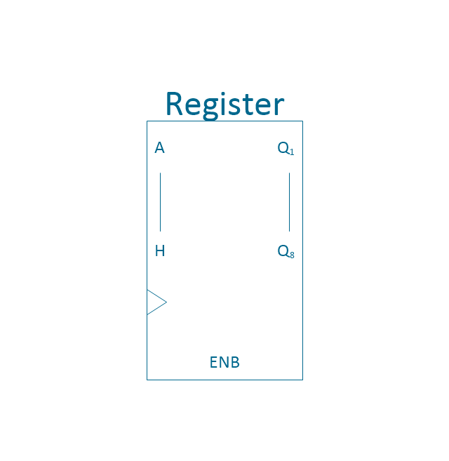
8-bit register
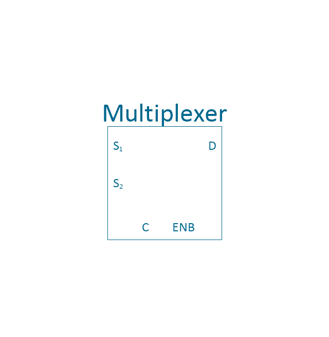
MUX 2
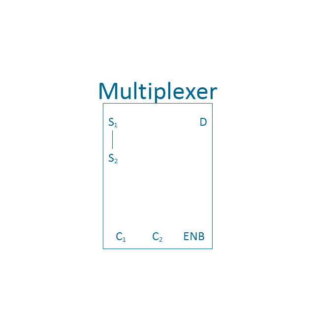
MUX 4
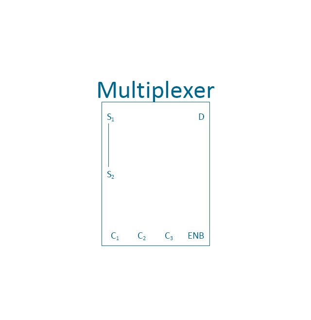
MUX 8
4-bit counter
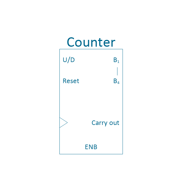
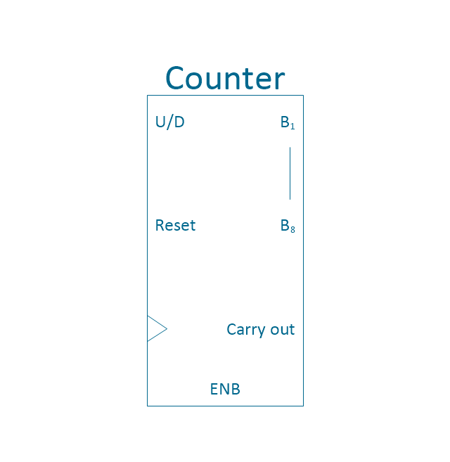
Counter
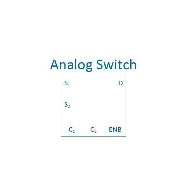
Analog switch 2
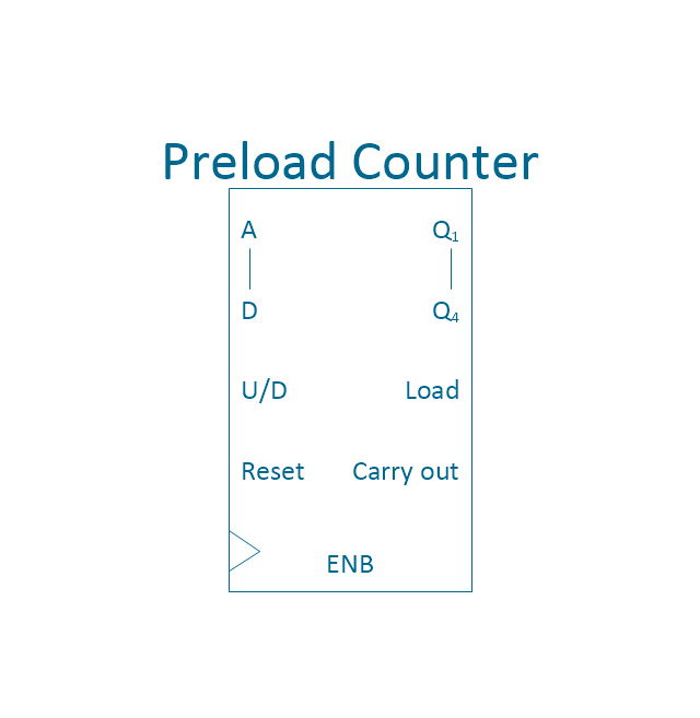
Preload counter 4
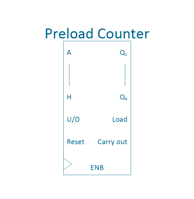
Preload Counter
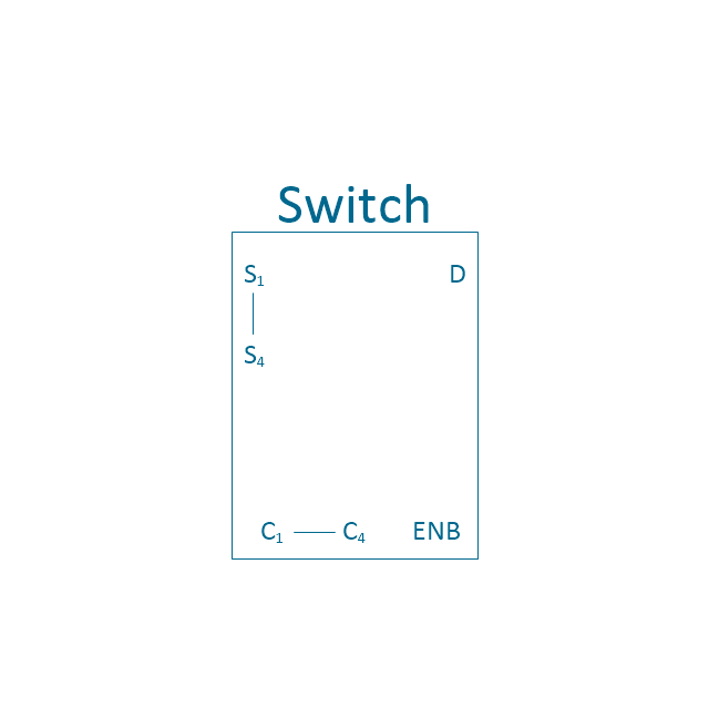
Analog switch 4
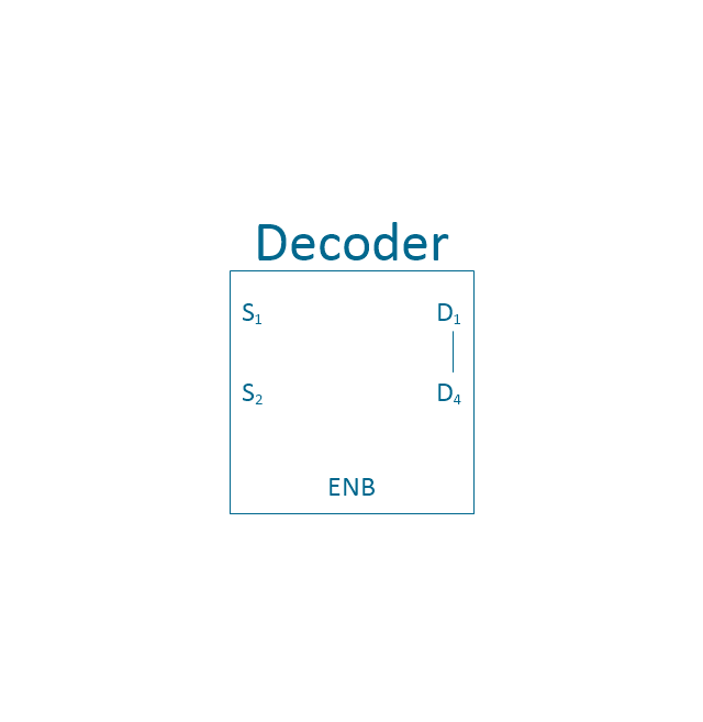
2 - 4 decoder
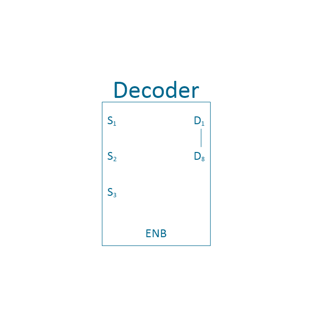
3 - 8 decoder
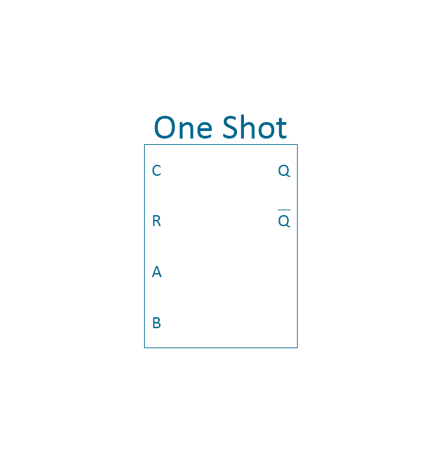
One shot
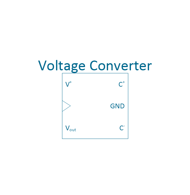
Voltage converter
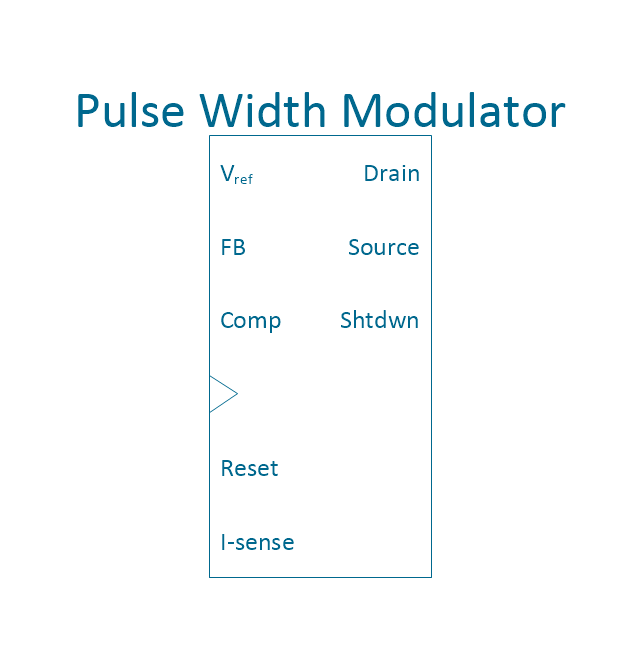
PWM
Horizontal extension
Horizontal extension 2
Horizontal extension, overline
Horizontal extension, overline 2
Vertical extension
Vertical extension 2

Vertical extension, overline
Vertical extension, overline 2

Switch point

Switch point 2

Ground

Ground 2

Wiring Diagrams with ConceptDraw DIAGRAM

Electrical Symbols — Integrated Circuit

- Cisco Optical. Cisco icons , shapes , stencils and symbols | Cisco ...
- How to Convert MS Visio ® 2003-2010 File to ConceptDraw PRO ...
- Visio Files and ConceptDraw | Integrated circuit - Vector stencils ...
- Electrical Symbols — Integrated Circuit | Electrical Symbols ...
- Cisco Optical. Cisco icons , shapes , stencils and symbols | Cisco ...
- Integrated circuit - Vector stencils library | Integrated circuit - Vector ...
- Electrical Symbols — Integrated Circuit | Network Diagram Software ...
- Integrated circuit - Vector stencils library | Extension Board Drawing ...
- Optical Mux Symbol
- Cisco Optical. Cisco icons , shapes , stencils and symbols | Cisco ...
- Cisco optical - Vector stencils library | Cisco Optical. Cisco icons ...
- Electrical Symbols , Electrical Diagram Symbols | Electrical Symbols ...
- Electrical Symbols , Electrical Diagram Symbols | How To use House ...
- Electrical Symbols , Electrical Diagram Symbols | How To use House ...
- Cisco optical - Vector stencils library | Telecommunication networks ...
- Cable TV - Vector stencils library | Cisco Optical. Cisco icons ...
- Cisco Optical. Cisco icons , shapes , stencils and symbols | Cisco ...
- Wiring Diagram
- Access and security - Vector stencils library | Design elements ...
- Cisco Optical. Cisco icons , shapes , stencils and symbols | Cisco ...