Interior Design Piping Plan - Design Elements

The vector stencils library "Pipes 2" contains 48 symbols of pipes. Use it for drawing plumbing and piping building plans, schematic diagrams, blueprints, or technical drawings of waste water disposal systems, hot and cold water supply systems in the ConceptDraw PRO diagramming and vector drawing software extended with the Plumbing and Piping Plans solution from the Building Plans area of ConceptDraw Solution Park.
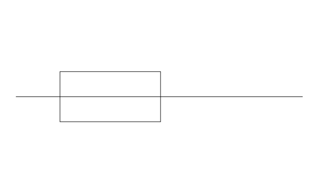
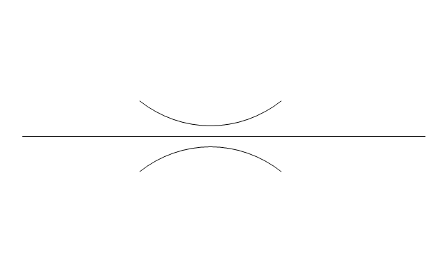
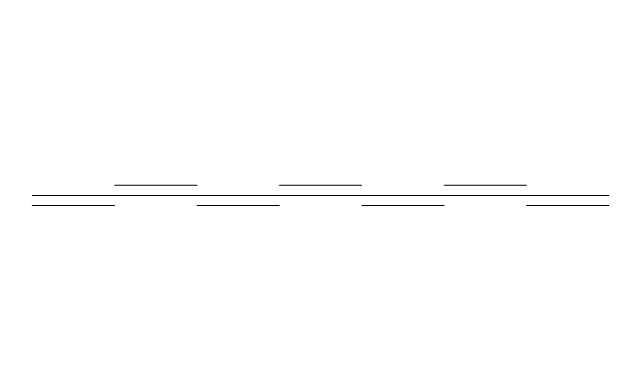
Crossing
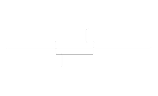
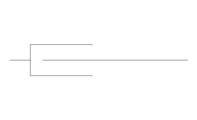
Junction
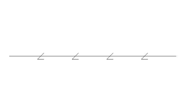
Basic support
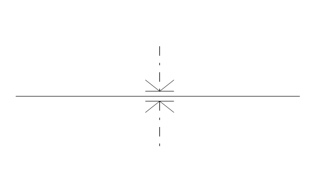
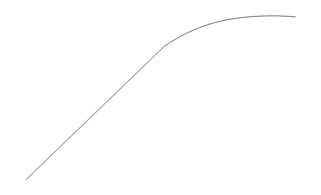
Guide 1
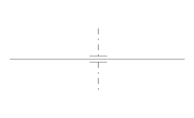
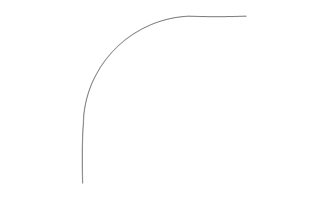
Guide 2
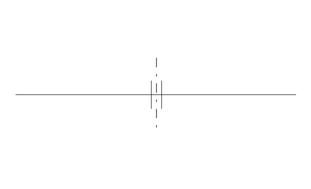
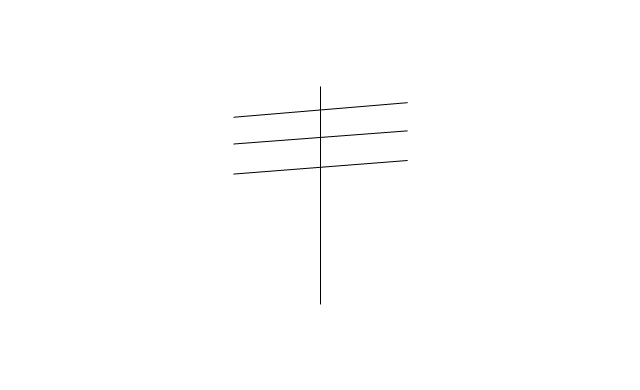
Guide 3
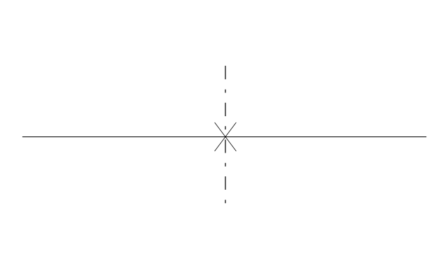
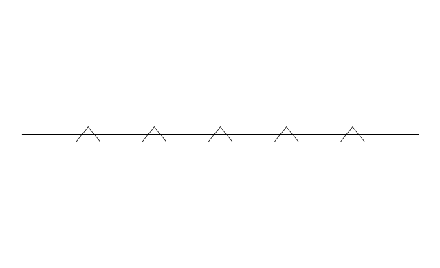
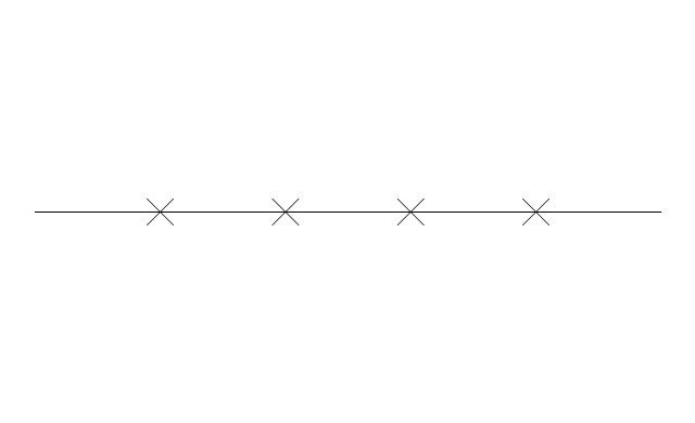
Stopper
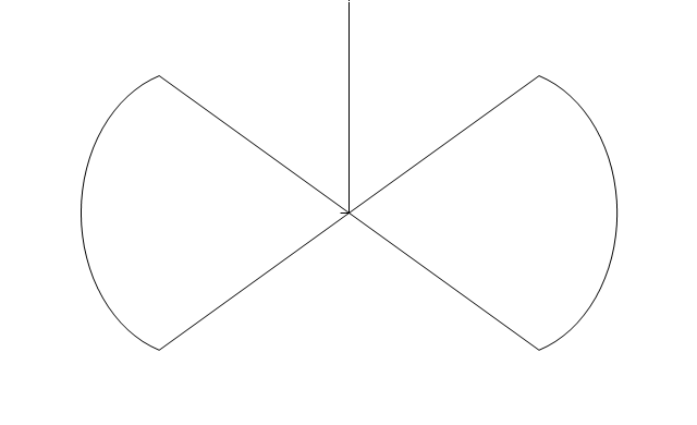
Anchor
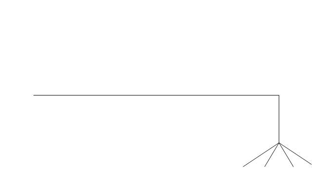
Support / anchor
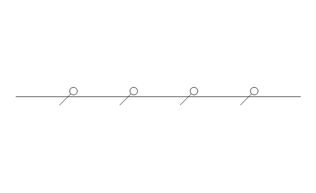
Hunger
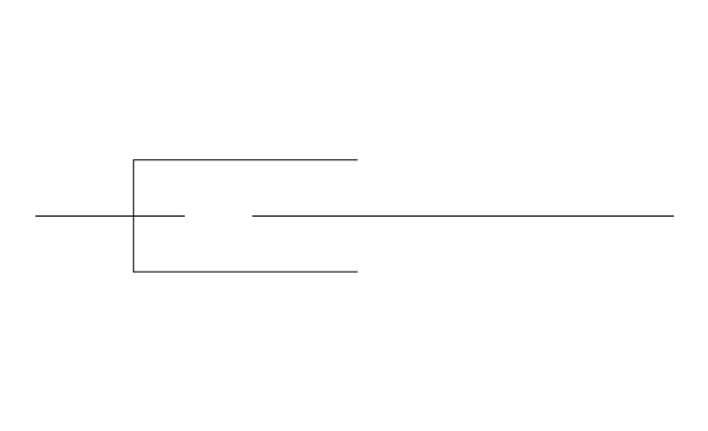
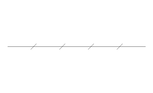
Cross
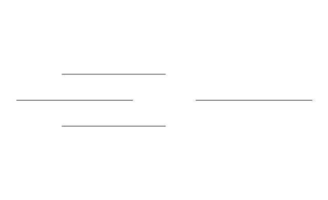
Double branch
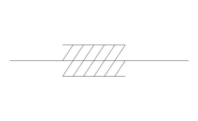
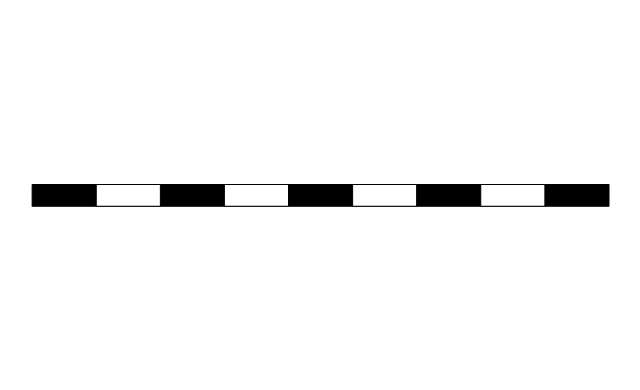
Jacketed
Sleeved
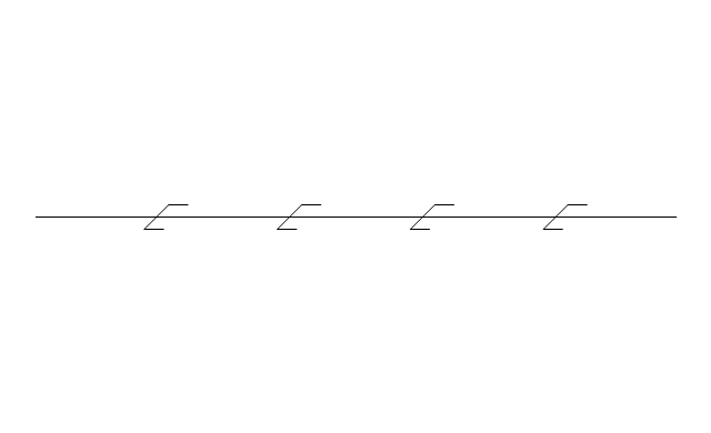
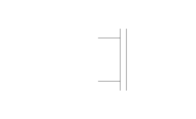
Sleeve joint
Expansion sleeve joint
Lagged
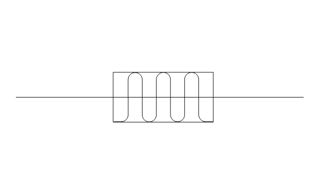
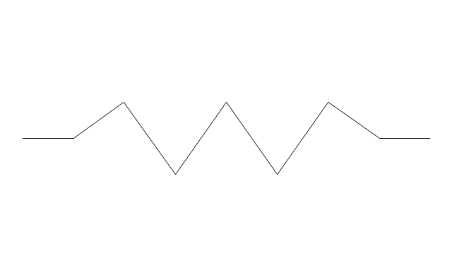
Bellows
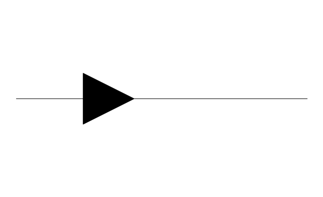
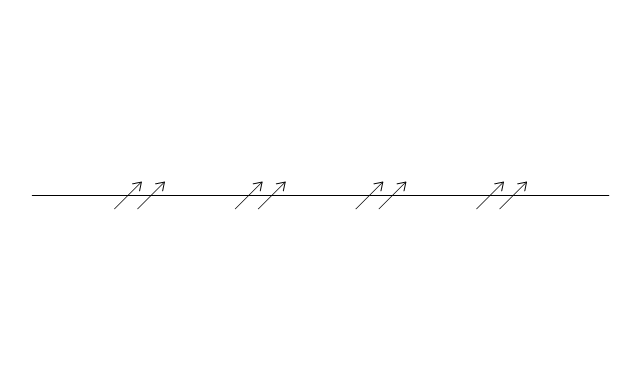
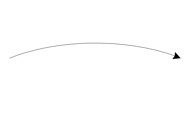
Flow indication
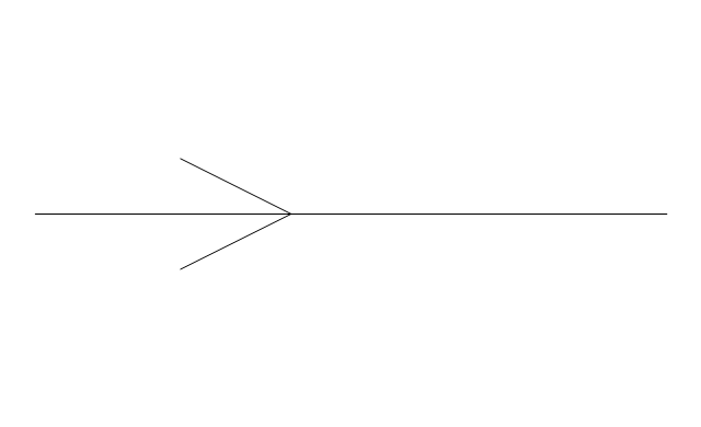
Flow indication 2
Reducer
Reducer,arrow
Pipe bore change
Flexibility provision
Sleeve extension
Flow restrictor
Elbow 45
Elbow 90
Heated or cooled
Pneumatic line
Signal line
Electric line
Hydraulic line
Capillary line
Internal connection
Route radiation
Mechanical linkage
Electrical device
Vibratory device
Weight device
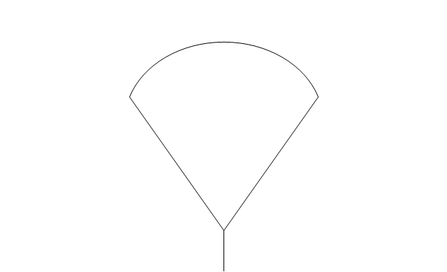
Spray device
Rotary motion
Stirring / fan
Access points
Trap
Expansion loop
Flexible hose
Flexible hose, flanged
 Plumbing and Piping Plans
Plumbing and Piping Plans solution extends ConceptDraw DIAGRAM.2.2 software with samples, templates and libraries of pipes, plumbing, and valves design elements for developing of water and plumbing systems, and for drawing Plumbing plan, Piping plan, PVC Pipe plan, PVC Pipe furniture plan, Plumbing layout plan, Plumbing floor plan, Half pipe plans, Pipe bender plans.
Electrical Symbols, Electrical Schematic Symbols

Electrical Symbols — Electrical Circuits

The vector stencils library "Pipes 2" contains 48 symbols of pipes. Use it for drawing plumbing and piping building plans, schematic diagrams, blueprints, or technical drawings of waste water disposal systems, hot and cold water supply systems in the ConceptDraw PRO diagramming and vector drawing software extended with the Plumbing and Piping Plans solution from the Building Plans area of ConceptDraw Solution Park.
Crossing
Junction
Basic support
Guide 1
Guide 2
Guide 3
Stopper
Anchor
Support / anchor
Hunger
Cross
Double branch
Jacketed
Sleeved
Sleeve joint
Expansion sleeve joint
Lagged
Bellows
Flow indication
Flow indication 2
Reducer
Reducer,arrow
Pipe bore change
Flexibility provision
Sleeve extension
Flow restrictor
Elbow 45
Elbow 90
Heated or cooled
Pneumatic line
Signal line
Electric line
Hydraulic line
Capillary line
Internal connection
Route radiation
Mechanical linkage
Electrical device
Vibratory device
Weight device
Spray device
Rotary motion
Stirring / fan
Access points
Trap
Expansion loop
Flexible hose
Flexible hose, flanged
The vector stencils libraries "Pipes 1" and "Pipes 2" contain 28 and 48 pipe, tubing and fitting symbols, respectively.
"Pipe is hollow cylinder used to conduct or transfer fluids (liquids and gases) from one place to other place. The main difference between pipe and tube is the critical dimension used to describe the pipe size or the tube size. For pipe, internal diameter (ID) roughly corresponds to the nominal pipe size for standard wall thickness. For tube, the outer diameter (OD) closely corresponds to the tube size. In current European standards pipes and tubes are nowadays described as outside diameter by wall thickness. The three standard types of pipe ends used in the piping industriesare; Plain Ends (PE), Threaded Ends (TE) and Beveled Ends (BE). In the past, many types of material have been used in conveying water from one point to another. Masonry and wood were probably the first materials used. Plastics are the newest, and are now being used quite extensively." [Piping. Wikipedia]
Use the design elements libraries "Pipes 1" and "Pipes 2" for drawing plumbing and piping building plans, schematic diagrams, blueprints, or technical drawings of waste water disposal systems, hot and cold water supply systems using the ConceptDraw PRO diagramming and vector drawing software.
The shapes libraries "Pipes 1" and "Pipes 2" are contained in the Plumbing and Piping Plans solution from the Building Plans area of ConceptDraw Solution Park.
Piping symbols
.png--diagram-flowchart-example.png)
The vector stencils library "Valves" contains 91 symbols of valves. Use it for drawing plumbing and piping plans, schematic diagrams and blueprints of industrial piping systems; process, vacuum, and fluids piping; hydraulics piping; air and gas piping; materials distribution; and liquid transfer systems in the ConceptDraw PRO diagramming and vector drawing software extended with the Plumbing and Piping Plans solution from the Building Plans area of ConceptDraw Solution Park.
In-line valve

3-way valve

4-way valve

Screw-down valve

Lock-shield valve

Reel valve

Relief valve

Relief valve 2

Relief valve 3

Relief valve 4

Angle valve

Angle valve 2

Angle valve 3

Angle valve 4

Check valve

Check valve 2

Screwdown valve

Float operated valve

Float operated valve 2

Flanged valve

Flanged valve 2

Butterfly valve

Butterfly valve 2

Globe valve

Globe valve 2

Globe valve 3

Needle valve

Needle valve 2

Needle valve 3

Needle valve 4

Diaphragm valve

Diaphragm valve 2

Diaphragm valve 3

Wedge gate valve

Parallel side valve

Gate valve

Ball valve

Ball valve 2

Ball valve 3

Powered control valve

Powered control valve 2

Powered control valve 3

Relief angle valve, pressure

Relief angle valve, vacuum

Reducing valve

Reducing valve 2

Plug valve

Plug valve 2

Plug valve, straight through

3-way plug valve

Plug valve, T-port

Plug valve, L-port

3-way plug valve

3-way plug valve 2

3-way plug valve 3

3-way plug valve, T-port

3-way plug valve, L-port

Mixing valve

Characterized port valve

Manual isolation

Power signal

Statically loaded

Spring loaded

Spring loaded 2

Remote control

Diaphragm

Diaphragm, positioner

Chain operated

Gear operated

Solenoid

Weight loaded

Weight loaded 2

Weight loaded 3

Float operated

Float operated 2

Dash-pot

Dash-pot 2

Piston

Quick opening

Quick opening 2

Quick closing

Quick closing 2

Connecting unit

Connecting unit 2

Connecting unit 3

Motor element

Motor element, opens on failure

Motor element, closes on failure

Motor element, retains position on fail

Motor element, safe direction

Regulating

- Expansion Joint Symbol
- Hydraulic Joint Symbol
- Symbol Of Pipe Joint
- Winter Sports | Mechanical Engineering | Pipe Joint Sign
- Hydraulics Pipe Joint Drawing
- Soldering Joints Symbol
- Design elements - Welding | Electric Symbol For Soldered Joint
- Symbol For Flanged Joint
- Pipe Joint Sembal
- What Is Symbol Of Square Pipe