Electrical Symbols — Logic Gate Diagram

Electrical Symbols, Electrical Diagram Symbols

Electrical Symbols — Lamps, Acoustics, Readouts

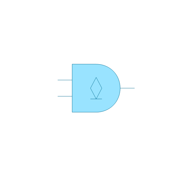
The vector stencils library "Logic gate diagram" contains 17 logical element symbols.
Use these shapes for drawing the logic gate diagrams in the ConceptDraw PRO diagramming and vector drawing software extended with the Electrical Engineering solution from the Engineering area of ConceptDraw Solution Park.
www.conceptdraw.com/ solution-park/ engineering-electrical
Use these shapes for drawing the logic gate diagrams in the ConceptDraw PRO diagramming and vector drawing software extended with the Electrical Engineering solution from the Engineering area of ConceptDraw Solution Park.
www.conceptdraw.com/ solution-park/ engineering-electrical
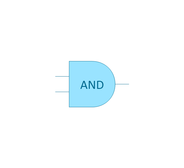
AND gate
OR gate

NOR gate (NOT OR)
-logic-gate-diagram---vector-stencils-library.png--diagram-flowchart-example.png)
NAND gate (NOT AND)
-logic-gate-diagram---vector-stencils-library.png--diagram-flowchart-example.png)
NOT gate (inverter)
-logic-gate-diagram---vector-stencils-library.png--diagram-flowchart-example.png)
EX-OR (Exclusive-OR) gate
-gate-logic-gate-diagram---vector-stencils-library.png--diagram-flowchart-example.png)
EX-NOR (Exclusive-NOR) gate
-gate-logic-gate-diagram---vector-stencils-library.png--diagram-flowchart-example.png)
Group

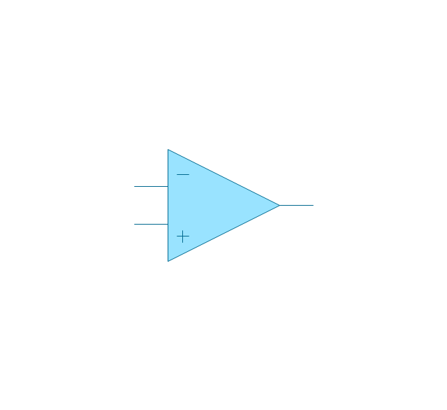
Operational Amplifier
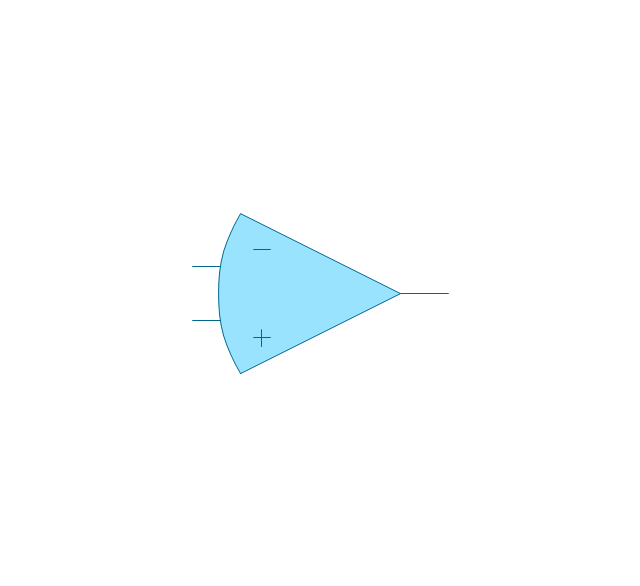
Alternative Operational Amplifier
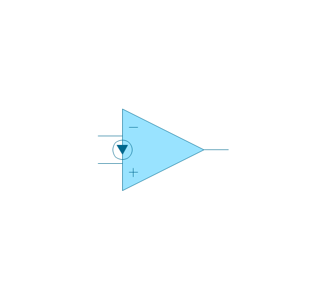
Norton op-amp
NOT gate (inverter)
-logic-gate-diagram---vector-stencils-library.png--diagram-flowchart-example.png)
NAND gate (NOT AND)
-logic-gate-diagram---vector-stencils-library.png--diagram-flowchart-example.png)
NOR gate (NOT OR)
-logic-gate-diagram---vector-stencils-library.png--diagram-flowchart-example.png)
Buffer

Gate with Open-Collector Output
Gate with Schmitt Trigger Input

Electrical Symbols — IGFET

Electrical Drawing Software and Electrical Symbols

Electrical Symbols — MOSFET

Electrical Symbols — Maintenance

Electrical Symbols, Electrical Schematic Symbols

Electrical Symbols — Analog and Digital Logic

- Design elements - Logic gate diagram | Draw The Logic Gate Symbol
- Electrical Engineering | Draw The Circut Sumbol X Or Gate
- Electrical Symbols — Logic Gate Diagram | Logic gate diagram ...
- Design elements - Logic gate diagram | Symbol Amplifier Diagram
- Logic gate diagram - Vector stencils library | Symbol Ex Nor Gate
- Draw The Traditional Logic Gate Symbol For And Or Not
- Logic Gate Drawing
- Symbol Of Gate In Drawing
- Draw Symbols Of And Gate
- Logic gate diagram - Template | Electrical Symbols — Logic Gate ...