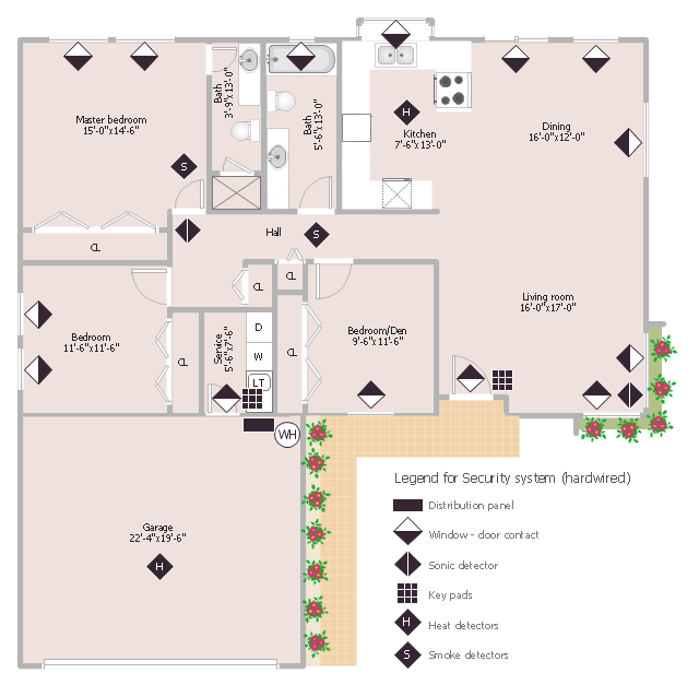
This sample was created on the base of the floor plan with security system device symbols from the website of the California State University, Sacramento. [imet.csus.edu/ imet1/ denyer/ mhs_ denyer/ drafting/ arch_ ch_ 31/ 31-28.jpg]
Legend for the security system hardware includes distribution panel, window-door contact, sonic detector, key pads, heat detectors, smoke detectors.
The example "Security system floor plan" was created using the ConceptDraw PRO diagramming and vector drawing software extended with the Security and Access Plans solution from the Building Plans area of ConceptDraw Solution Park.
Security system floor plan
Electrical and Telecom Plan Software

How To use House Electrical Plan Software


 Office Layout Plans
Office layouts and office plans are a special category of building plans and are often an obligatory requirement for precise and correct construction, design and exploitation office premises and business buildings. Designers and architects strive to make office plans and office floor plans simple and accurate, but at the same time unique, elegant, creative, and even extraordinary to easily increase the effectiveness of the work while attracting a large number of clients.
This cafe electrical floor plan sample shows the outlet and switch layout.
"An electrical drawing, is a type of technical drawing that shows information about power, lighting, and communication for an engineering or architectural project. Any electrical working drawing consists of "lines, symbols, dimensions, and notations to accurately convey an engineering's design to the workers, who install the electrical system on the job".
A complete set of working drawings for the average electrical system in large projects usually consists of:
(1) A plot plan showing the building's location and outside electrical wiring.
(2) Floor plans showing the location of electrical systems on every floor.
(3) Power-riser diagrams showing panel boards.
(4) Control wiring diagrams.
(5) Schedules and other information in combination with construction drawings.
Electrical drafters prepare wiring and layout diagrams used by workers who erect, install, and repair electrical equipment and wiring in communication centers, power plants, electrical distribution systems, and buildings." [Electrical drawing. Wikipedia]
The outlet and switch layout example "Cafe electrical floor plan" was created using the ConceptDraw PRO diagramming and vector drawing software extended with the Electric and Telecom Plans solution from the Building Plans area of ConceptDraw Solution Park.
Outlet and switch layout

Building Drawing Software for Design Office Layout Plan


Building Plan Software. Building Plan Examples

The vector stencils library "Electrical and telecom" contains 83 symbols of electrical and telecommunication equipment for electrical drawings and wiring diagrams of buildings, communication centers, power plants and electrical distribution systems.
"An electrical drawing, is a type of technical drawing that shows information about power, lighting, and communication for an engineering or architectural project." [Electrical drawing. Wikipedia]
Use the design elements library "Electrical and telecom" to design your own electrical drawings, plot plans of the building outside electrical wiring, floor plans with electrical and telecommunication systems layout, power-riser diagrams with panel boards, control wiring diagrams and cabling layout schemes, reflected ceiling plans and lighting panels layouts using the ConceptDraw PRO diagramming and vector drawing software.
The shapes library "Electrical and telecom" is included in the Electric and Telecom Plans solution from the Building Plans area of ConceptDraw Solution Park.
Electrical and telecom symbols

 Fire and Emergency Plans
It's a good idea to have an emergency exit strategy in place for your home or business. ConceptDraw gives you the tools to create your own fire and emergency plan, tailored to your setting.
Interior Design Plumbing - Design Elements

Interior Design Office Layout Plan Design Element

Office Design Software

Electrical Drawing Software and Electrical Symbols

The vector stencils library "Qualifying" contains 56 qualifying symbols of radiation, polarity, phase, windings, wire, ground, connection, connector, coaxial, electret.
Use these signs to annotate or specify characteristics of objects in electrical drawings, electronic schematics, circuit diagrams, electromechanical drawings, and wiring diagrams, cabling layout diagrams.
"An electrical drawing, is a type of technical drawing that shows information about power, lighting, and communication for an engineering or architectural project. Any electrical working drawing consists of "lines, symbols, dimensions, and notations to accurately convey an engineering's design to the workers, who install the electrical system on the job".
A complete set of working drawings for the average electrical system in large projects usually consists of:
(1) A plot plan showing the building's location and outside electrical wiring.
(2) Floor plans showing the location of electrical systems on every floor.
(3) Power-riser diagrams showing panel boards.
(4) Control wiring diagrams.
(5) Schedules and other information in combination with construction drawings.
Electrical drafters prepare wiring and layout diagrams used by workers who erect, install, and repair electrical equipment and wiring in communication centers, power plants, electrical distribution systems, and buildings." [Electrical drawing. Wikipedia]
The signs example "Design elements - Qualifying" was drawn using the ConceptDraw PRO diagramming and vector drawing software extended with the Electrical Engineering solution from the Engineering area of ConceptDraw Solution Park.
Qualifying symbols

 Reflected Ceiling Plans
Reflected Ceiling Plans solution is effective tool for architects, designers, electricians, and other people which every day need convenient tool for representing their ceiling ideas. Use it to create without efforts professional Reflected Ceiling plans and Reflective Ceiling plans, showing the location of light fixtures, drywall or t-bar ceiling patterns, lighting panels, and HVAC grilles and diffusers that may be suspended from the ceiling.
- How To use House Electrical Plan Software | Security system floor ...
- How To use House Electrical Plan Software | Design elements ...
- Design elements - Qualifying | Cafe electrical floor plan | Panel ...
- How To use House Electrical Plan Software | Cafe electrical floor ...
- Distribution Panel Design Diagram Symbol Diagram
- Cafe electrical floor plan | Design elements - Qualifying | Electrical ...
- Distribution Board Wiring Symbol
- Panel Board Symbol Floor Plan
- How To use House Electrical Plan Software | Electrical Drawing ...
- Schematic Symbol Of Power Distribution Panel
- Security system floor plan | How To use House Electrical Plan ...
- Lighting and switch layout | Reflected ceiling plan | Classroom ...
- Design elements - Qualifying | Cafe electrical floor plan | How To ...
- How to Draw a Security and Access Floor Plan | Security system ...
- Toilet Symbol Floor Plan
- Security system floor plan | Design elements - Doors and windows ...
- Wiring Diagram Main Distribution Board Electrical Equipment Ligting
- How to Draw a Security and Access Floor Plan | Physical Security ...
- Design elements - Doors and windows | Security system floor plan ...
- How to Draw a Security and Access Floor Plan | Network Layout ...