"Network topology is the arrangement of the various elements (links, nodes, etc.) of a computer network. Essentially, it is the topological structure of a network, and may be depicted physically or logically. Physical topology refers to the placement of the network's various components, including device location and cable installation, while logical topology shows how data flows within a network, regardless of its physical design. Distances between nodes, physical interconnections, transmission rates, and/ or signal types may differ between two networks, yet their topologies may be identical. The study of network topology recognizes eight basic topologies: Point-to-point, Bus, Star, Ring or circular, Mesh, Tree, Hybrid, Daisy chain." [Network topology. Wikipedia]
The computer network topologies diagram example was created using the ConceptDraw PRO diagramming and vector drawing software extended with the Computer and Networks solution from the Computer and Networks area of ConceptDraw Solution Park.
The computer network topologies diagram example was created using the ConceptDraw PRO diagramming and vector drawing software extended with the Computer and Networks solution from the Computer and Networks area of ConceptDraw Solution Park.
Network topologies

"Logical topology, or signal topology, is the arrangement of devices on a computer network and how they communicate with one another. How devices are connected to the network through the actual cables that transmit data, or the physical structure of the network, is called the physical topology. Physical topology defines how the systems are physically connected. It represents the physical layout of the devices on the network. The logical topology defines how the systems communicate across the physical topologies.
Logical topologies are bound to network protocols and describe how data is moved across the network. ...
EXAMPLE : twisted pair Ethernet is a logical bus topology in a physical star topology layout. while IBM's token ring is a logical ring topology, it is physically set up in star topology." [Logical topology. Wikipedia]
This Cisco logical computer network diagram example was created using the ConceptDraw PRO diagramming and vector drawing software extended with the Cisco Network Diagrams solution from the Computer and Networks area of ConceptDraw Solution Park.
Logical network topology diagram

Network Diagram Examples


Basic Network Diagram

Network Diagram Software

Network Diagramming with ConceptDraw DIAGRAM

Network Drawing Software

The vector stencils library "Cisco LAN" contains 23 symbols of local area network devices and equipment for drawing Cisco LAN diagrams using the ConceptDraw PRO diagramming and vector drawing software.
"Network topology describes the layout of interconnections between devices and network segments. At the Data Link Layer and Physical Layer, a wide variety of LAN topologies have been used, including ring, bus, mesh and star, but the most common LAN topology in use today is switched Ethernet. At the higher layers, the Internet Protocol (TCP/ IP) has become the standard, replacing NetBEUI, IPX/ SPX, AppleTalk and others.
Simple LANs generally consist of one or more switches. A switch can be connected to a router, cable modem, or ADSL modem for Internet access. Complex LANs are characterized by their use of redundant links with switches using the spanning tree protocol to prevent loops, their ability to manage differing traffic types via quality of service (QoS), and to segregate traffic with VLANs. A LAN can include a wide variety of network devices such as switches, firewalls, routers, load balancers, and sensors.
LANs can maintain connections with other LANs via leased lines, leased services, or the Internet using virtual private network technologies. Depending on how the connections are established and secured in a LAN, and the distance involved, a LAN may also be classified as a metropolitan area network (MAN) or a wide area network (WAN)." [Local area network. Wikipedia]
The example "Design elements - Cisco LAN" is included in the Cisco Network Diagrams solution from the Computer and Networks area of ConceptDraw Solution Park.
Cisco LAN symbols
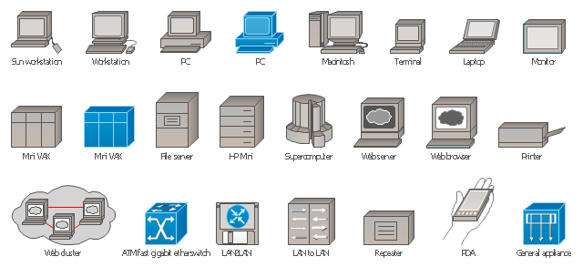
The vector stencils library "Computer network" contains 29 icon symbols of devices and equipment.
Use these shapes for drawing LAN, MAN and WAN diagrams at physical and logical levels, network architecture, topology, wiring and layout schematic and plans.
This library for the ConceptDraw PRO diagramming and vector drawing software is included in the Computer and Networks solution from the Computer and Networks area of ConceptDraw Solution Park.
Computer network icons
- Bus network topology diagram | Communication ... - Conceptdraw.com
- Network Diagram Examples | Network Topology | How to draw Metro ...
- Network Diagram Software Physical Network ... - Conceptdraw.com
- Network Diagramming with ConceptDraw PRO | Cisco Network ...
- Network Hubs | ConceptDraw PRO Network Diagram Tool | 10Base ...
- Network Topology | ConceptDraw PRO Network Diagram Tool ...
- Wireless router network diagram - Conceptdraw.com
- Basic Diagramming | Engineering | Home area network (HAN ...
- Network Diagram Software LAN Diagrams ... - Conceptdraw.com
- Cisco LAN. Cisco icons, shapes, stencils and symbols | Cisco ...
- How to Draw a Computer Network Diagrams | Computer and ...
- Network Gateway Router | Network Diagram Software Home Area ...
- How to Draw a Computer Network Diagrams ... - Conceptdraw.com
- Communication network diagram | Computers and Communications ...
- Locations of Workgroup and network routers | Cisco Network ...
- How to Draw a Computer Network Diagrams | Fishbone Diagram ...
- How to Draw a Computer Network Diagrams | Computer network ...
- Network Diagram Examples | Network Architecture | Network ...
- How to Draw a Computer Network Diagrams | Network diagrams ...
- How to Draw a Computer Network Diagrams | Network Diagram ...