Campus Area Networks (CAN). Computer and Network Examples


Metropolitan area networks (MAN). Computer and Network Examples
. Computer and Network Examples")
Fishbone Diagram Problem Solving

Local area network (LAN). Computer and Network Examples
 diagram")
Draw Network Diagram based on Templates and Examples

Network diagrams with ConceptDraw DIAGRAM

Entity Relationship Diagram - ERD - Software for Design Crows Foot ER Diagrams
_Win_Mac.png)

Design Element: Network Layout for Network Diagrams
.png)
Network Diagram Software Home Area Network
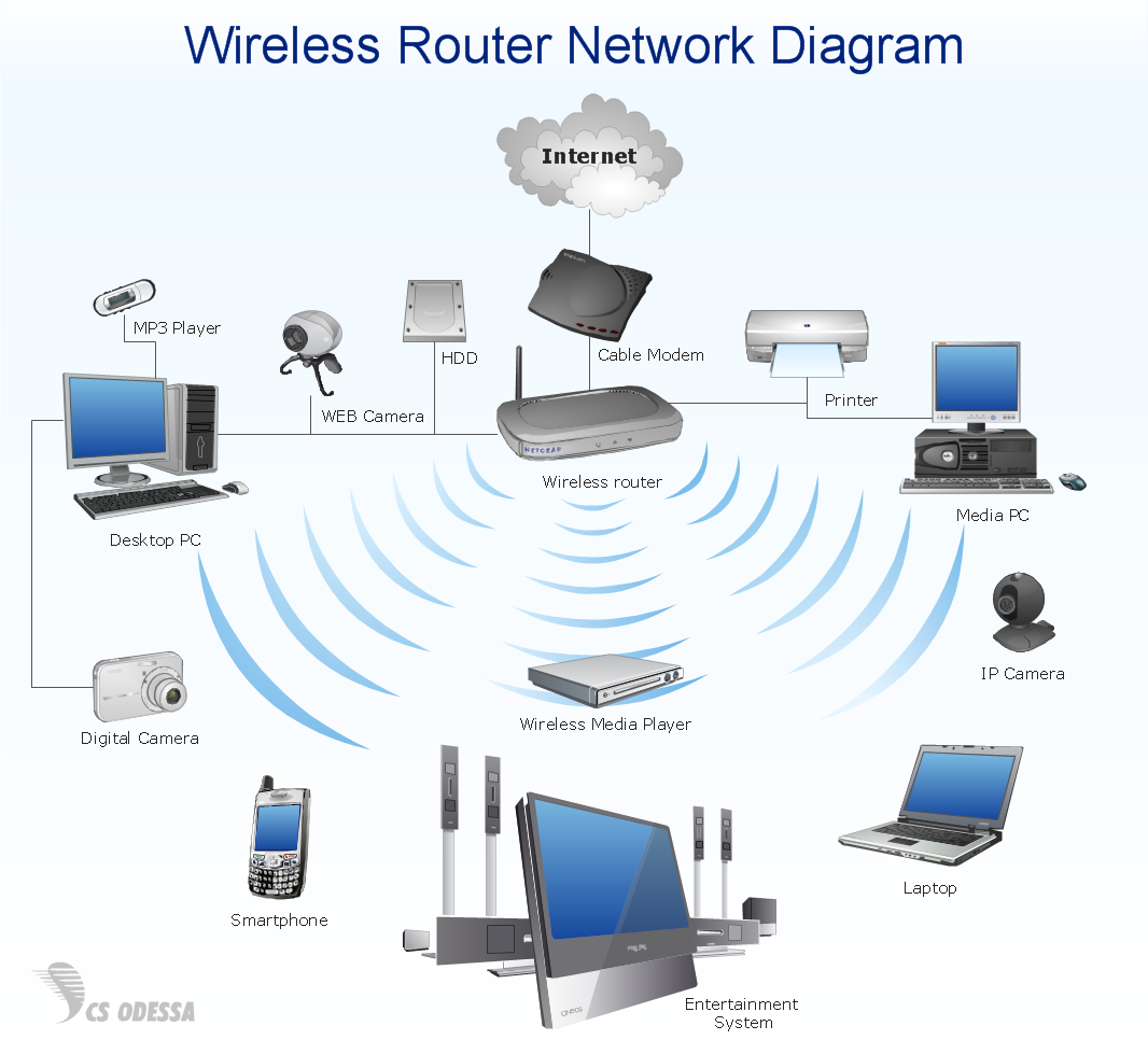
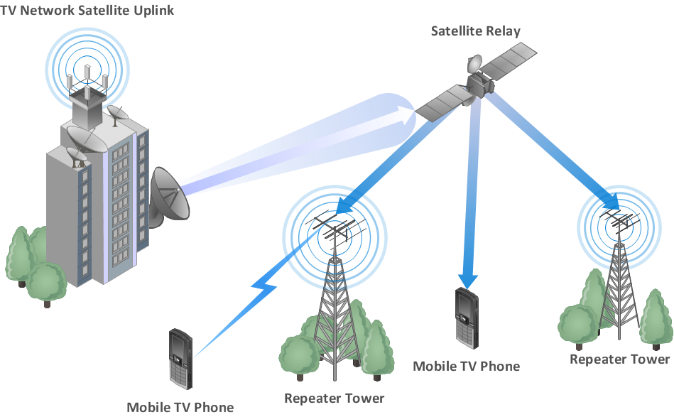
Wireless Network WAN
- Firewall between LAN and WAN | Computer network diagram ...
- Computer and Networks Area | Sketch A Scale Of Wan
- Network Security Diagrams | Draw Network Diagram based on ...
- Cisco WAN - Vector stencils library | Design elements - Cisco WAN ...
- Local area network ( LAN ). Computer and Network Examples ...
- Cisco network diagram - Template | Design elements - Cisco WAN ...
- M Area Network Diagram
- Design elements - Cisco WAN | Cisco WAN - Vector stencils library ...
- Star Network Topology | Computer network diagram - Template ...
- Cisco WAN - Vector stencils library | Network Diagram Examples ...