Drawing Illustration

Process Diagrams

Bar Diagram Math

Affinity Diagram

 Basic Divided Bar Diagrams
This solution extends the capabilities of ConceptDraw PRO v10.3.0 (or later) with templates, samples and a library of vector stencils for drawing Divided Bar diagrams.
This PFD sample was redesigned from the Wikipedia file: NaturalGasCondensate.png.
"This is a schematic flow diagram of a typical facility for separating and recovering liquid condensate from raw natural gas."
[en.wikipedia.org/ wiki/ File:NaturalGasCondensate.png]
"Natural-gas condensate is a low-density mixture of hydrocarbon liquids that are present as gaseous components in the raw natural gas produced from many natural gas fields. It condenses out of the raw gas if the temperature is reduced to below the hydrocarbon dew point temperature of the raw gas.
The natural gas condensate is also referred to as simply condensate, or gas condensate, or sometimes natural gasoline because it contains hydrocarbons within the gasoline boiling range. Raw natural gas may come from any one of three types of gas wells:
(1) Crude oil wells - Raw natural gas that comes from crude oil wells is called associated gas. This gas can exist separate from the crude oil in the underground formation, or dissolved in the crude oil.
(2) Dry gas wells - These wells typically produce only raw natural gas that does not contain any hydrocarbon liquids. Such gas is called non-associated gas.
(3) Condensate wells - These wells produce raw natural gas along with natural gas liquid. Such gas is also non-associated gas and often referred to as wet gas." [Natural-gas condensate. Wikipedia]
The process flow diagram example "Natural gas condensate - PFD" was drawn using the ConceptDraw PRO software extended with the Chemical and Process Engineering solution from the Chemical and Process Engineering area of ConceptDraw Solution Park.
Process flow diagram (PFD)
-natural-gas-condensate---pfd.png--diagram-flowchart-example.png)
How to Draw a Natural Landscape

Beautiful Nature Scene: Drawing

 Chemical and Process Engineering
This chemical engineering solution extends ConceptDraw PRO v.9.5 (or later) with process flow diagram symbols, samples, process diagrams templates and libraries of design elements for creating process and instrumentation diagrams, block flow diagrams (BFD
Drawing a Nature Scene

Affinity Diagram

Beauty of Event-driven Process Chain (EPC) diagrams
")
How to Draw Workflow Diagram

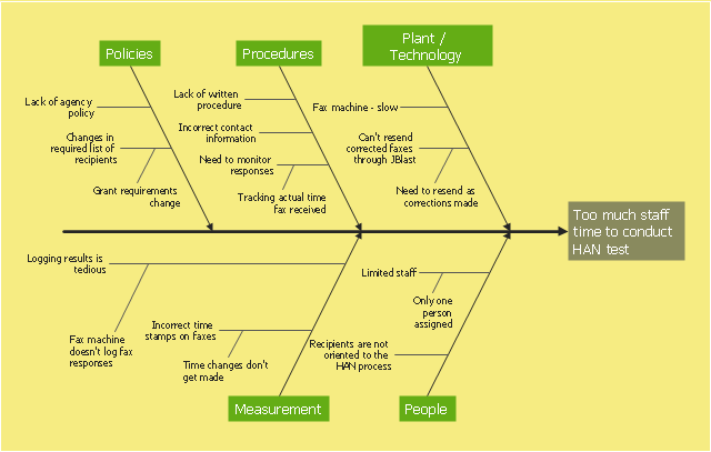
This example was created on the base of the figure from the website of Minnesota Department of Health. [health.state.mn.us/ divs/ opi/ qi/ images/ fishbone_ ex.png]
"Minnesota’s Health Alert Network (HAN) enables public health staff, tribal governments, health care providers, emergency workers, and others working to protect the public to exchange information during a disease outbreak, environmental threat, natural disaster, or act of terrorism." [health.state.mn.us/ han/ ]
The fishbone diagram example "HAN project" was created using the ConceptDraw PRO diagramming and vector drawing software extended with the Fishbone Diagrams solution from the Management area of ConceptDraw Solution Park.
Ishikawa diagram
Process Flow Diagram

- Diagrams Of Natural Resources
- Graphs Pie Diagrams For Natural Resources
- Natural Resources Diagrams
- Outline Diagram Of Natural Resources Pie Chart
- Easy Natural Diagrams
- Oil And Gas Production Process Flow Diagram
- Pie Charts | Bar Diagram Math | Pie Graph Worksheets ...
- Energy resources diagram | Conservation Of Natural Resources ...
- Block Flow Diagram Of Natural Gas Processing Plant
- Pie Graph Worksheets | Pie Charts | Bar Diagram Math | Natural ...
- How To Start Natural Resource Using Diagram
- Natural Resources Pie Chart
- Bar Diagram Math | Pie Charts | Divided Bar Diagrams | Mangement ...
- Picture Graphs | Bar Diagram Math | Infographic Maker | Examples ...
- Amine treating unit schematic diagram | Natural gas condensate ...
- Energy Pyramid Diagram | Resources and energy - Vector stencils ...
- Bar Diagram Math | Scientific Symbols Chart | Business People ...
- Natural Gas Plant Process Flow Diagram
- Bar Diagram Math | Divided Bar Diagrams | Basic Diagramming ...
- Crude oil distillation unit - PFD | Natural gas condensate - PFD ...