Cisco Products Additional. Cisco icons, shapes, stencils and symbols

The vector stencils library "AWS Database" contains 30 Amazon Web Services database icons: Amazon DynamoDB symbols, Amazon Relational Database Service symbols, Amazon ElasticCache symbols, Amazon SimpleDB symbols, Amazon Redshift symbols.
Use it to draw AWS architecture diagrams of your cloud service.
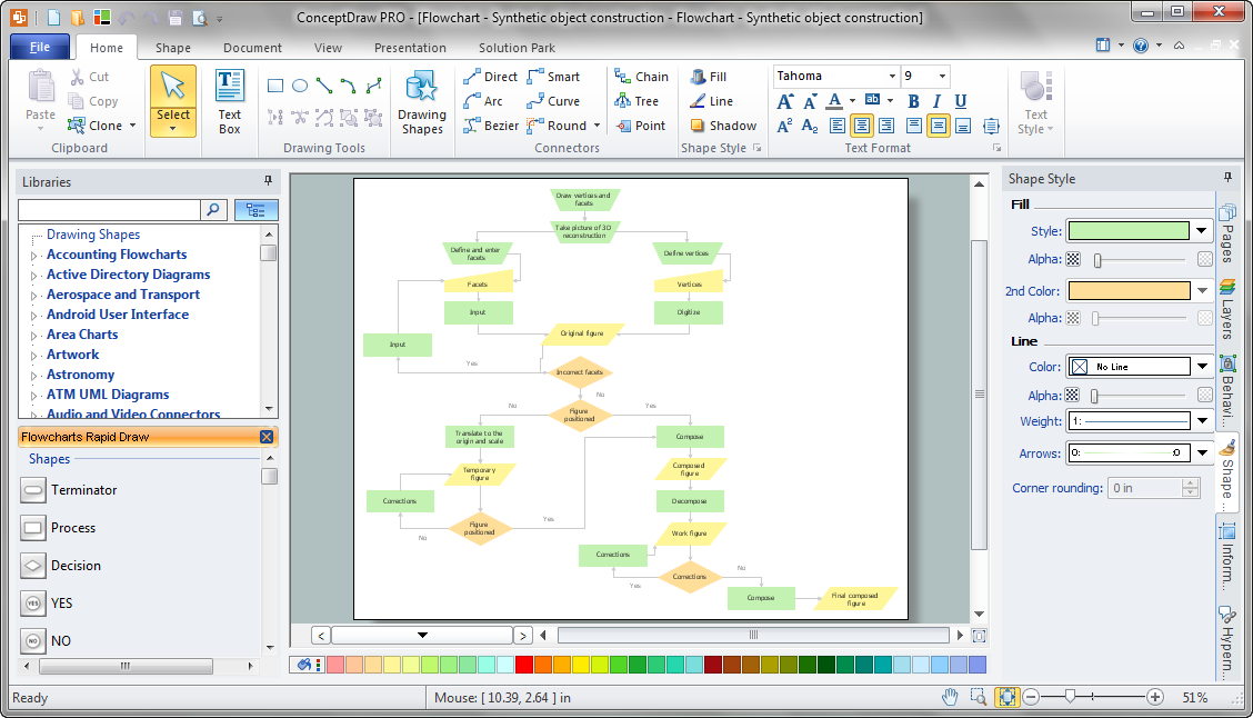
The symbols example "AWS Database - Vector stencils library" was created using the ConceptDraw PRO diagramming and vector drawing software extended with the AWS Architecture Diagrams solution from the Computer and Networks area of ConceptDraw Solution Park.
Use it to draw AWS architecture diagrams of your cloud service.
The symbols example "AWS Database - Vector stencils library" was created using the ConceptDraw PRO diagramming and vector drawing software extended with the AWS Architecture Diagrams solution from the Computer and Networks area of ConceptDraw Solution Park.
DynamoDB

Table
Item
Items
Attribute

Attributes
Global secondary index

Amazon RDS

RDS DB instance
RDS DB instance standby (Multi-AZ)
-aws-database---vector-stencils-library.png--diagram-flowchart-example.png)
RDS DB instance read replica
MySQL DB instance
Oracle DB instance
MS SQL
instance
PostgreSQL instance
SQL master

SQL slave
PIOP
ElastiCache

Cache node

Redis
Memcached

Amazon SimpleDB
Domain
Amazon Redshift

Solid state disks
DW2 Dense Compute
DW1 Dense Compute

Sales Process Flowchart Symbols

UML Collaboration Diagram (UML2.0)


Data Flow Diagram Model

Flow Diagrams
Diagramming Software for Design UML Object Diagrams

Ordering Process Flowchart. Flowchart Examples
The vector stencils library "Cisco network topology" contains 89 symbols of Cisco network devices and design elements for drawing computer network topology diagrams.
"There are two basic categories of network topologies:
(1) Physical topologies,
(2) Logical topologies.
The shape of the cabling layout used to link devices is called the physical topology of the network. This refers to the layout of cabling, the locations of nodes, and the interconnections between the nodes and the cabling. The physical topology of a network is determined by the capabilities of the network access devices and media, the level of control or fault tolerance desired, and the cost associated with cabling or telecommunications circuits.
The logical topology in contrast, is the way that the signals act on the network media, or the way that the data passes through the network from one device to the next without regard to the physical interconnection of the devices." [Network topology. Wikipedia]
The symbols example "Cisco network topology - Vector stencils library" was created using the ConceptDraw PRO diagramming and vector drawing software extended with the Cisco Network Diagrams solution from the Computer and Networks area of ConceptDraw Solution Park.
www.conceptdraw.com/ solution-park/ computer-networks-cisco
Router

Broadband router

Router firewall

Wireless router

Workgroup switch

ATM switch

ISDN switch

Multilayer switch

Protocol translator

Communications server

Transpath

Bridge

Terminal server

Route switch processor

Content engine (cache director)
-cisco-network-topology---vector-stencils-library.png--diagram-flowchart-example.png)
Management engine (ME 1100)
-cisco-network-topology---vector-stencils-library.png--diagram-flowchart-example.png)
Switch processor

ITP

Voice gateway

BBSM

ATA

SIP Proxy server

NetRanger

Cisco 1000

IP

System controller

ACE

Directory server

ADM

Cisco Unity Express

Unity server

Cisco security

CallManager

DSLAM

H.323

CDM (Content Distribution Manager)
-cisco-network-topology---vector-stencils-library.png--diagram-flowchart-example.png)
ICM

Access point

Wireless bridge

Wireless connectivity

Guard

Mobile access router

Carrier Routing System (CRS)
-cisco-network-topology---vector-stencils-library.png--diagram-flowchart-example.png)
Vault

Workstation

PC

Macintosh

Cloud, gold

Cloud, white

Cloud, standard color

Cisco security management

PBX

DPT

Government building

Headquarters, blue

Router in building

Man

Woman

Workgroup switch, subdued

Router, subdued

File server

Firewall, horizontal

Firewall, vertical

Firewall, vertical, subdued

Lock

Key

Lock and key

Car

Truck

File cabinet

Breakout box

Breakout box, blue

Host

Relational database

Modem

BBS (Bulletin Board System)
-cisco-network-topology---vector-stencils-library.png--diagram-flowchart-example.png)
Satellite

Satellite dish

UPS

RPS

MAU

PAD

PAD X.28

Diskette

Contact center

Page icon
Antenna

Antenna, blue

Radio tower

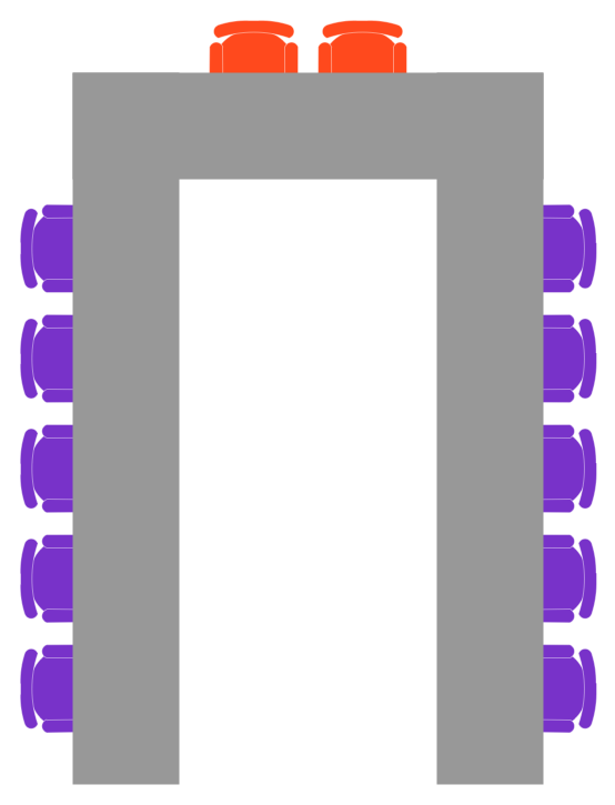
Table Seating Chart Template
- Azure Management | AWS Database - Vector stencils library ...
- Azure Architecture | Redis Erd Diagram
- AWS Database - Vector stencils library | Design elements - AWS ...
- Flow Chart Online | Flowchart Examples | Online Flow Chart | Web ...
- Data Base Symbols
- Postgre Visio
- Design elements - AWS Database | AWS Database - Vector stencils ...
- AWS Database - Vector stencils library | Computer Network ...
- Design elements - AWS Database | Diagramming software for ...
- Cisco network topology - Vector stencils library | Logical symbols ...