Example of DFD for Online Store (Data Flow Diagram) DFD Example


Design Data Flow. DFD Library

Examples Flowchart
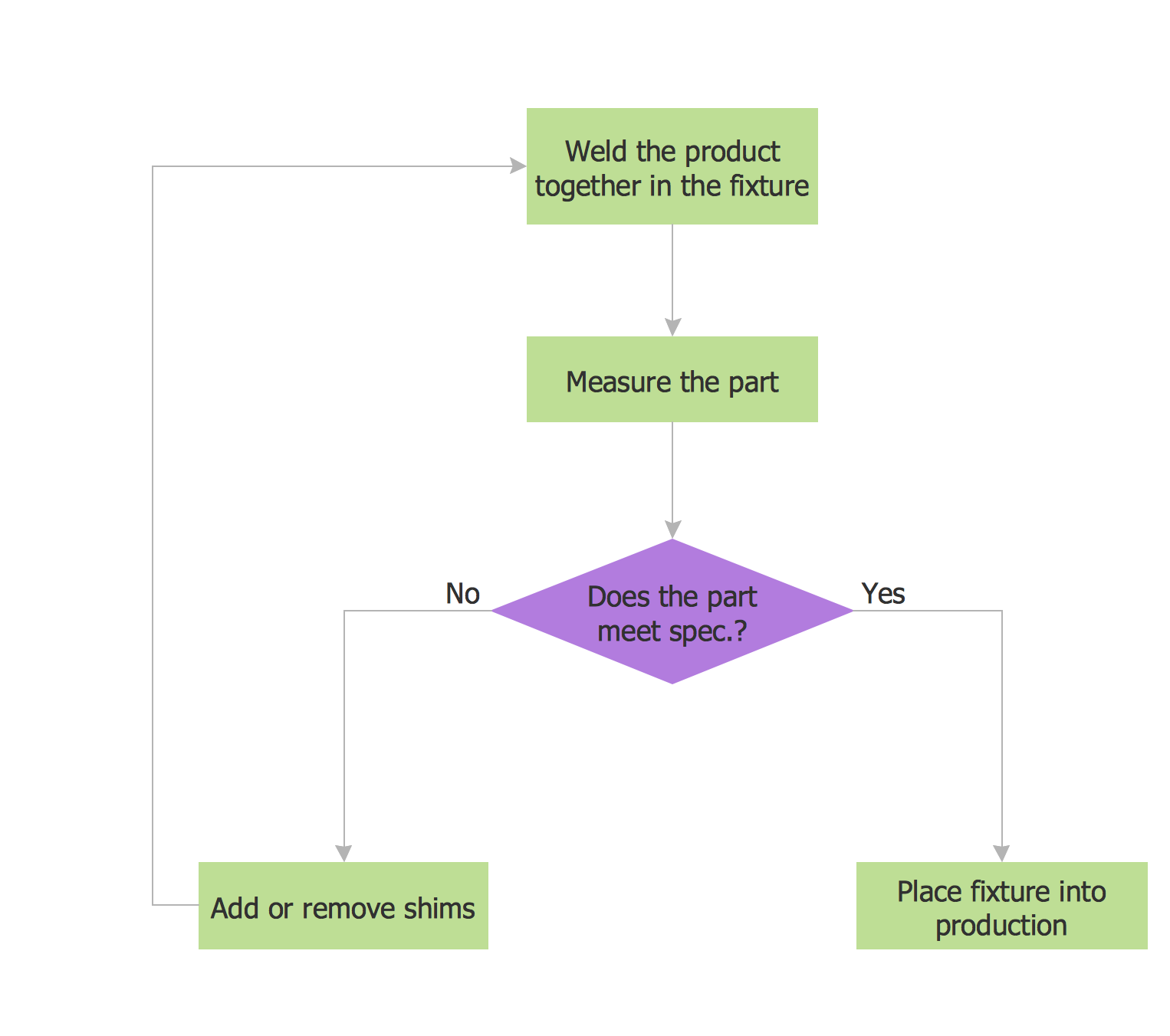
ConceptDraw DIAGRAM diagramming and vector drawing software provides the unique Flowcharts Solution from the "Diagrams" Area of ConceptDraw Solution Park with variety of vector objects libraries and collection of examples Flowchart. Each example flowchart included in Flowcharts solution is a real help in drawing process, it can be the good base or perfect source of inspiration.
UML Diagram for System

Geo Map - Australia

ConceptDraw DIAGRAM ER Diagram Tool

 Audit Flowcharts
Audit flowcharts solution extends ConceptDraw DIAGRAM software with templates, samples and library of vector stencils for drawing the audit and fiscal flow charts.
ERD Symbols and Meanings


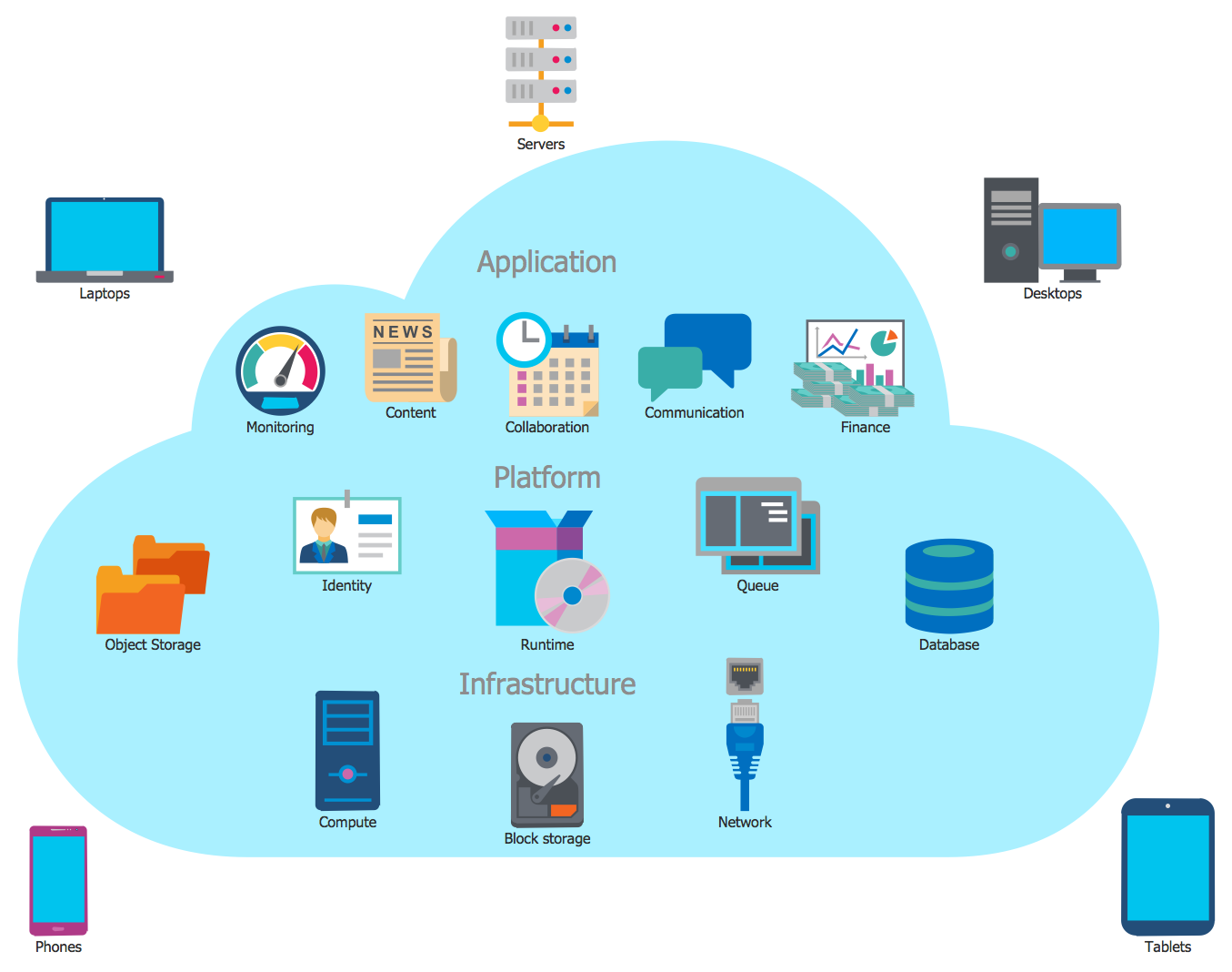
Cloud Computing Architecture
IT Security Solutions

- Jewellery Shop Management System Data Flow Diagram
- Er Diagram Of Jewellery Shop Management System Project
- Only Jewellery Management System Data Flow Diagram
- Example of DFD for Online Store ( Data Flow Diagram ) DFD ...
- Use Case Diagram For Online Jewellery Shopping
- Business Process Flow Diagram | Example of DFD for Online Store ...
- Jewellery Shop Management System Project Er Diagram Dfd
- Er Diagram Of Shop Management System
- Database Flowchart Symbols | Data Flow Diagram | Process ...
- How to Connect Social Media DFD Flowchart with Action Maps ...