JSD - Jackson system development

Developing Entity Relationship Diagrams

Entity Relationship Diagram Software Engineering

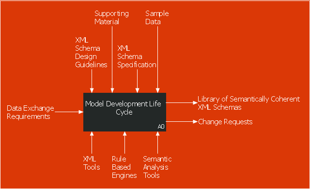
This IDEF0 diagram sample was created on the base of the figure from the website of the Engineering Laboratory of the National Institute of Standards and Technology (NIST). [mel.nist.gov/ msidlibrary/ doc/ kc_ morris/ gsa-final_ files/ image002.gif]
"The systems development life cycle (SDLC), also referred to as the application development life-cycle, is a term used in systems engineering, information systems and software engineering to describe a process for planning, creating, testing, and deploying an information system. The systems development life-cycle concept applies to a range of hardware and software configurations, as a system can be composed of hardware only, software only, or a combination of both." [Systems development life cycle. Wikipedia]
The IDEF0 diagram example "Model development life cycle" was created using the ConceptDraw PRO diagramming and vector drawing software extended with the IDEF0 Diagrams solution from the Software Development area of ConceptDraw Solution Park.
IDEF0 diagram
SSADM Diagram

Software Diagram Templates
Software Diagram Examples and Templates

Software Diagrams

Object-Oriented Development (OOD) Method

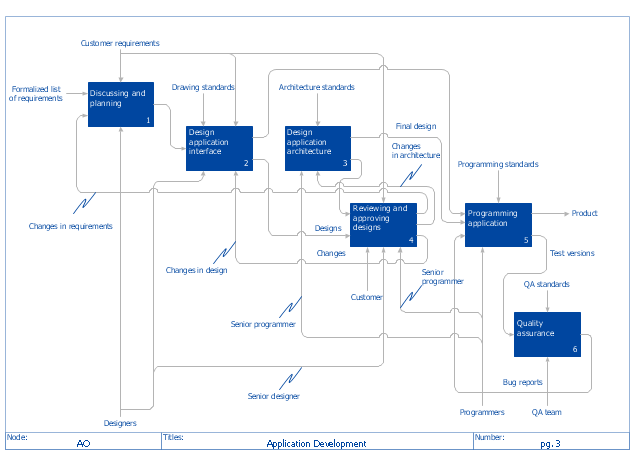
"The IDEF0 Functional Modeling method is designed to model the decisions, actions, and activities of an organization or system. ...
IDEF0 includes both a definition of a graphical modeling language (syntax and semantics) and a description of a comprehensive methodology for developing models. ...
IDEF0 is used to show data flow, system control, and the functional flow of lifecycle processes. IDEF0 is capable of graphically representing a wide variety of business, manufacturing and other types of enterprise operations to any level of detail. It provides rigorous and precise description, and promotes consistency of usage and interpretation." [IDEF0. Wikipedia]
The IDEF0 diagram example "Application development" was created using the ConceptDraw PRO diagramming and vector drawing software extended with the IDEF0 Diagrams solution from the Software Development area of ConceptDraw Solution Park.
IDEF0 diagram example
- Systems development life cycle | SSADM Diagram | Process ...
- Venn Diagram In Community Development
- Venn Diagram Examples for Problem Solving. Environmental Social ...
- Process Flowchart | JSD - Jackson system development | Systems ...
- Path to sustainable development | Venn Diagram Examples for ...
- Application development - IDEF0 diagram | How to Create an IDEF0 ...
- Agile Methodology | SSADM Diagram | Basic Flowchart Symbols ...
- Software Development Flow Diagram
- Application Development Flow Chart
- Sustainable development | Venn Diagram | Path to sustainable ...