"Physical topology refers to the placement of the network's various components, including device location and cable installation...
The shape of the cabling layout used to link devices is called the physical topology of the network. This refers to the layout of cabling, the locations of nodes, and the interconnections between the nodes and the cabling. The physical topology of a network is determined by the capabilities of the network access devices and media, the level of control or fault tolerance desired, and the cost associated with cabling or telecommunications circuits." [Network topology. Wikipedia]
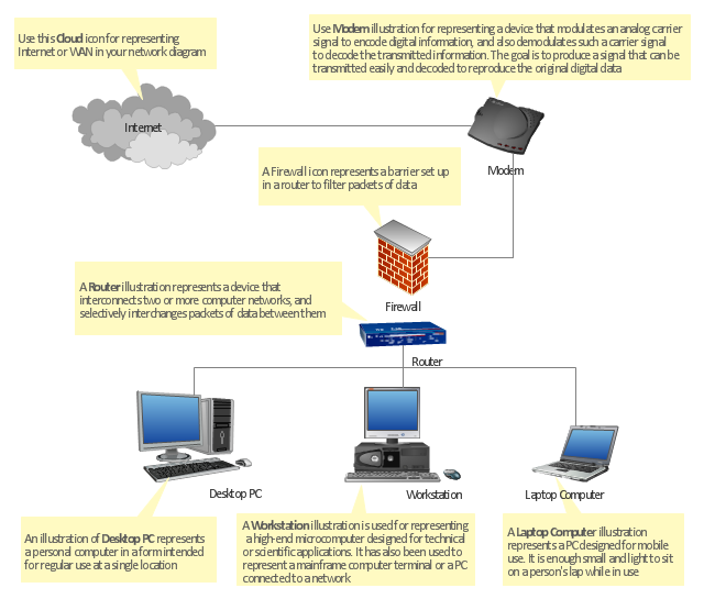
This physical LAN diagram example was created using the ConceptDraw PRO diagramming and vector drawing software extended with the Computer and Networks solution from the Computer and Networks area of ConceptDraw Solution Park.
The shape of the cabling layout used to link devices is called the physical topology of the network. This refers to the layout of cabling, the locations of nodes, and the interconnections between the nodes and the cabling. The physical topology of a network is determined by the capabilities of the network access devices and media, the level of control or fault tolerance desired, and the cost associated with cabling or telecommunications circuits." [Network topology. Wikipedia]
This physical LAN diagram example was created using the ConceptDraw PRO diagramming and vector drawing software extended with the Computer and Networks solution from the Computer and Networks area of ConceptDraw Solution Park.
LAN physical topology

Used Solutions
Network Diagram Examples


Network Diagram Software Logical Network Diagram

"At different scales diagrams may represent various levels of network granularity. At the LAN level, individual nodes may represent individual physical devices, such as hubs or file servers, while at the WAN level, individual nodes may represent entire cities. In addition, when the scope of a diagram crosses the common LAN/ MAN/ WAN boundaries, representative hypothetical devices may be depicted instead of showing all actually existing nodes. For example, if a network appliance is intended to be connected through the Internet to many end-user mobile devices, only a single such device may be depicted for the purposes of showing the general relationship between the appliance and any such device." [Computer network diagram. Wikipedia]
The physical LAN and WAN diagram template for the ConceptDraw PRO diagramming and vector drawing software is included in the Computer and Networks solution from the Computer and Networks area of ConceptDraw Solution Park.
The physical LAN and WAN diagram template for the ConceptDraw PRO diagramming and vector drawing software is included in the Computer and Networks solution from the Computer and Networks area of ConceptDraw Solution Park.
Physical LAN and WAN diagram template
 Cisco Network Diagrams
Cisco Network Diagrams solution extends ConceptDraw DIAGRAM with the best characteristics of network diagramming software. Included samples, templates and libraries of built-in standardized vector Cisco network icons and Cisco symbols of computers, network devices, network appliances and other Cisco network equipment will help network engineers, network designers, network and system administrators, as well as other IT professionals and corporate IT departments to diagram efficiently the network infrastructure, to visualize computer networks topologies, to design Cisco computer networks, and to create professional-looking Cisco Computer network diagrams, Cisco network designs and schematics, Network maps, and Network topology diagrams in minutes.
"Fault-tolerant computer systems are systems designed around the concepts of fault tolerance. In essence, they have to be able to keep working to a level of satisfaction in the presence of faults. ...
Most fault-tolerant computer systems are designed to be able to handle several possible failures, including hardware-related faults such as hard disk failures, input or output device failures, or other temporary or permanent failures; software bugs and errors; interface errors between the hardware and software, including driver failures; operator errors, such as erroneous keystrokes, bad command sequences, or installing unexpected software; and physical damage or other flaws introduced to the system from an outside source." [Fault-tolerant computer system. Wikipedia]
The computer network diagram example "Cisco LAN fault-tolerance system" was created using the ConceptDraw PRO diagramming and vector drawing software extended with the Cisco Network Diagrams solution from the Computer and Networks area of ConceptDraw Solution Park.
LAN fault-tolerance system

Used Solutions
 Computer Network Diagrams
Computer Network Diagrams solution extends ConceptDraw DIAGRAM software with samples, templates and libraries of vector icons and objects of computer network devices and network components to help you create professional-looking Computer Network Diagrams, to plan simple home networks and complex computer network configurations for large buildings, to represent their schemes in a comprehensible graphical view, to document computer networks configurations, to depict the interactions between network's components, the used protocols and topologies, to represent physical and logical network structures, to compare visually different topologies and to depict their combinations, to represent in details the network structure with help of schemes, to study and analyze the network configurations, to communicate effectively to engineers, stakeholders and end-users, to track network working and troubleshoot, if necessary.
- Local area network ( LAN ). Computer and Network Examples ...
- Logical network topology diagram | Network Topologies | Network ...
- Simple Lan Diagram
- Physical LAN and WAN diagram - Template | Cisco Network ...
- Diagram Physical Topologies | Hotel Network Topology Diagram ...
- Diagram Og Wireless Lan
- Network Diagram Examples | Physical LAN and WAN diagram ...
- Lan Diagram Example
- Lan Diagram
- Diagram Of A Lan Network With Switches And Gateways
- Physical LAN topology diagram | ConceptDraw PRO Network ...
- Network Glossary Definition | Example Of Block Diagram Of Lan Vs ...
- Network Gateway Router | Hotel Network Topology Diagram | LAN ...
- Lan Diagrams
- Network Glossary Definition | Network Diagram Software LAN ...
- Cisco LAN fault-tolerance system - diagram
- Home area networks (HAN). Computer and Network Examples ...
- Network Layout Floor Plans | Network Layout | Network Diagram ...
- Physical LAN and WAN diagram - Template | Wide area network ...
- Network Diagram Software LAN Network Diagrams & Diagrams for ...