UML Class Diagram Notation

UML Class Diagram Generalization Example UML Diagrams

UML Diagram Types List

"Metadata is "data about data". The term is ambiguous, as it is used for two fundamentally different concepts (types). Structural metadata is about the design and specification of data structures and is more properly called "data about the containers of data"; descriptive metadata, on the other hand, is about individual instances of application data, the data content.
Metadata are traditionally found in the card catalogs of libraries. As information has become increasingly digital, metadata are also used to describe digital data using metadata standards specific to a particular discipline. By describing the contents and context of data files, the quality of the original data/ files is greatly increased. For example, a webpage may include metadata specifying what language it is written in, what tools were used to create it, and where to go for more on the subject, allowing browsers to automatically improve the experience of users." [Metadata. Wikipedia]
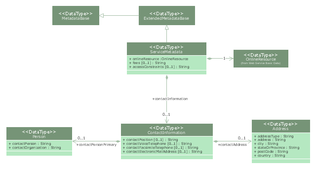
The UML class diagram example "Metadata information model" was created using the ConceptDraw PRO diagramming and vector drawing software extended with the Rapid UML solution from the Software Development area of ConceptDraw Solution Park.
Metadata are traditionally found in the card catalogs of libraries. As information has become increasingly digital, metadata are also used to describe digital data using metadata standards specific to a particular discipline. By describing the contents and context of data files, the quality of the original data/ files is greatly increased. For example, a webpage may include metadata specifying what language it is written in, what tools were used to create it, and where to go for more on the subject, allowing browsers to automatically improve the experience of users." [Metadata. Wikipedia]
The UML class diagram example "Metadata information model" was created using the ConceptDraw PRO diagramming and vector drawing software extended with the Rapid UML solution from the Software Development area of ConceptDraw Solution Park.
UML class diagram
UML Block Diagram

UML Class Diagram. Design Elements

Booch OOD Diagram

UML Interaction Overview Diagram. Design Elements

UML Deployment Diagram. Design Elements

Interaction Overview Diagram


- IDEF4 Standard | Define Class Diagram
- UML Class Diagram Generalization Example UML Diagrams ...
- Class UML Diagram for Bank Account System | UML package ...
- Data modeling with ConceptDraw PRO | Uml Database Notation
- Rapid UML | ATM UML Diagrams | Rapid UML | Class Diagram ...
- Class UML Diagram for Bank Account System | Bank UML Diagram ...
- UML Deployment Diagram Example - ATM System UML diagrams ...
- Accounting Flowcharts | Draw A Use Case And Class Diagram For ...
- UML Use Case Diagram Example Registration System | UML ...
- Class Diagram For Online Education System