The vector stencils library "Interactions" contains 18 interaction elements icons: mouse pointers, splitters, select frame.
Use it to design graphic user interface (GUI) prototypes of your software applications for Windows 8.
"In computing, a pointer or mouse cursor (as part of a personal computer WIMP style of interaction) is a graphical image on the computer monitor or other display device. The pointer echoes movements of the pointing device, commonly a mouse or touchpad, and signals the point where actions of the user take place. It can be used to select and move other graphical user interface elements, and is distinct from the cursor, which responds to keyboard input. The cursor may also be repositioned using the pointer.
The pointer commonly appears as an angled arrow, (angled because historically that improved appearance on low resolution screens) but it can vary within different programs or operating systems. The use of a pointer is employed when the input method, or pointing device, is a device that can move fluidly across a screen and select or highlight objects on the screen." [Pointer (graphical user interfaces). Wikipedia]
The design elements example "Interactions - Vector stencils library" was created using the ConceptDraw PRO diagramming and vector drawing software extended with the Windows 8 User Interface solution from the Software Development area of ConceptDraw Solution Park.
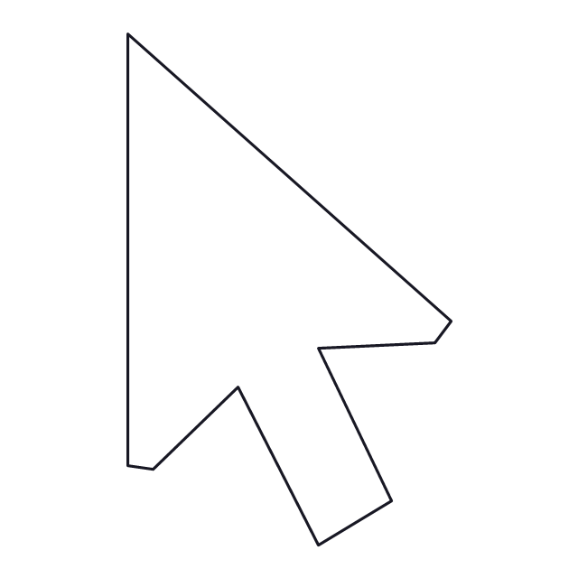
Normal select pointer
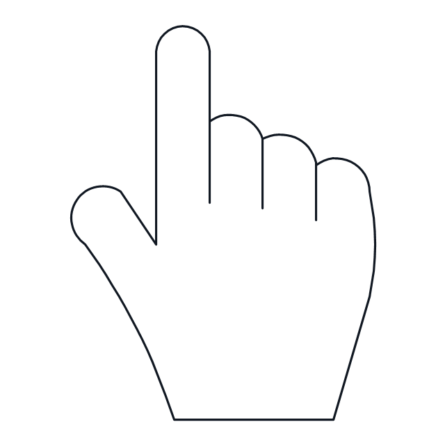
Link select pointer
Text select pointer
Precision select pointer
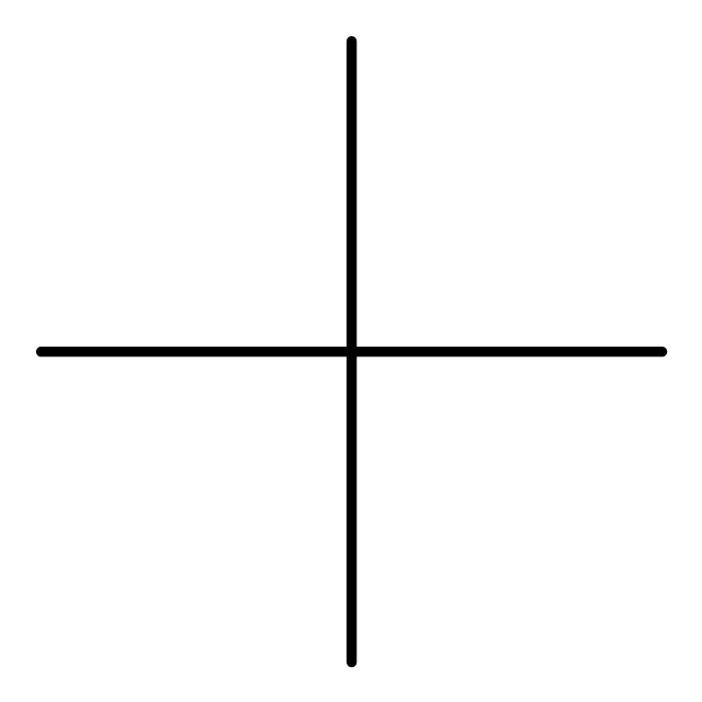
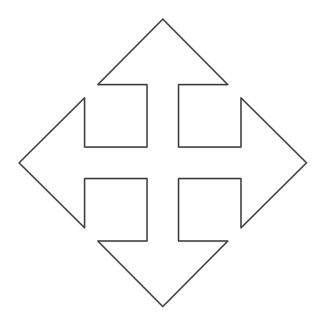
Move pointer
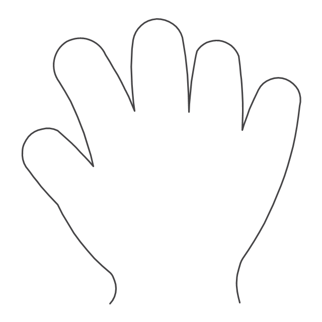
Pan pointer
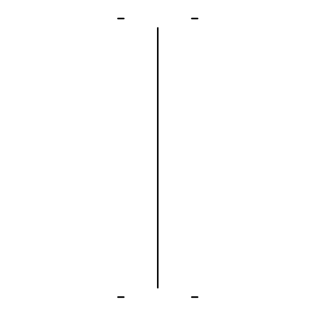
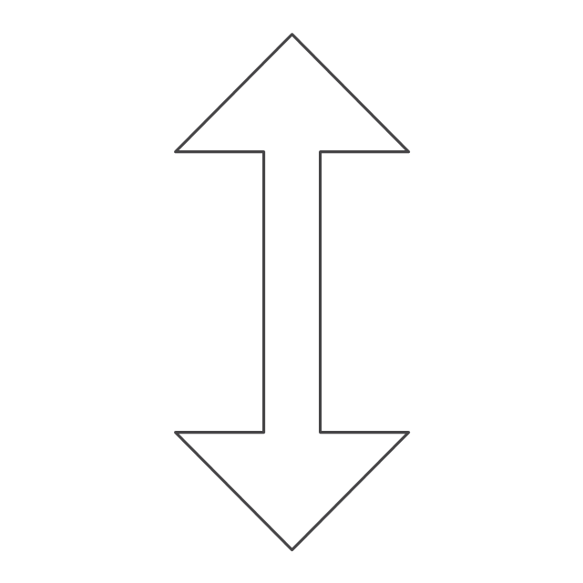
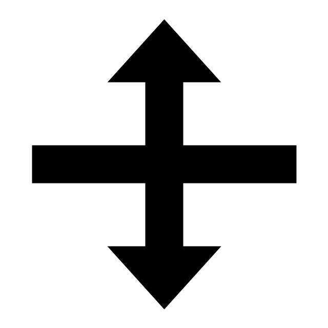
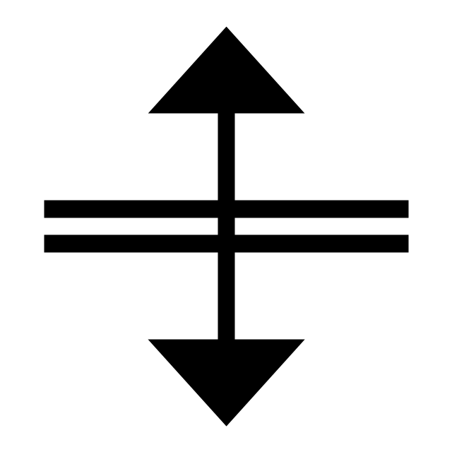
Vertical resize pointer
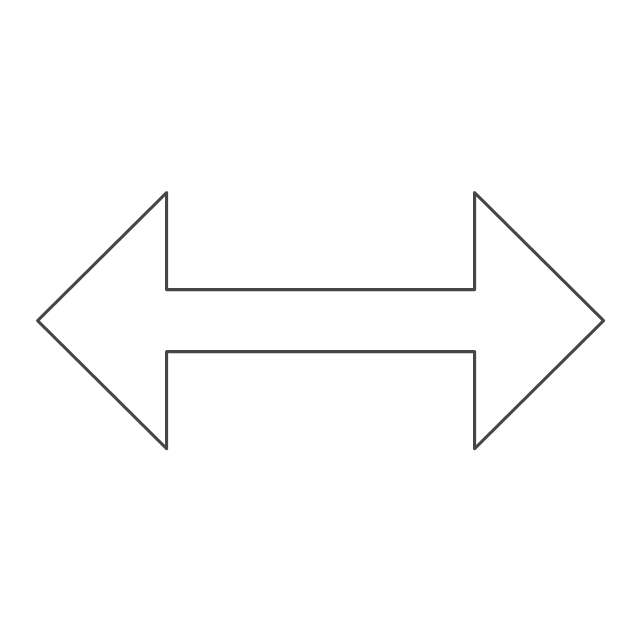
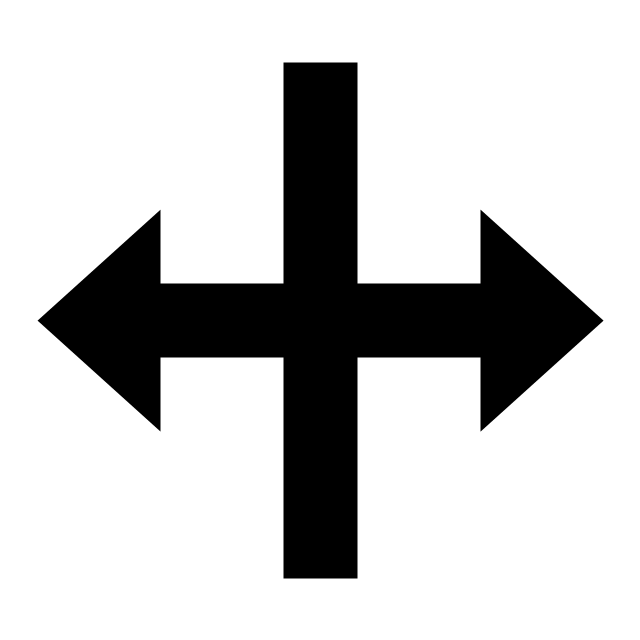
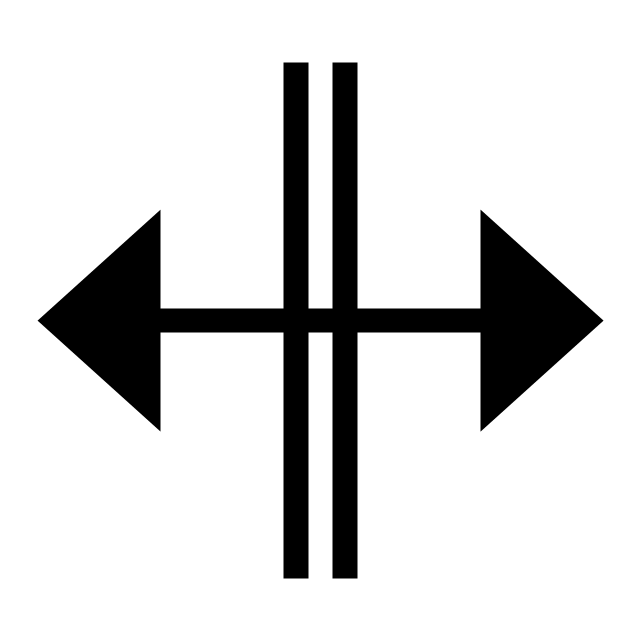
Horizontal resize pointer
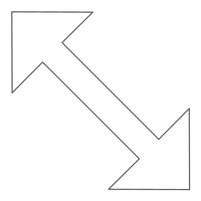
Diagonal resize pointer
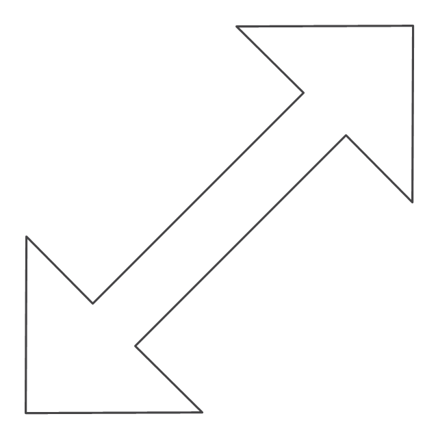
Diagonal resize pointer 2
Row resize pointer
Column resize pointer
Window splitter - vertically
Window splitter - horizontally
Working in background pointer

Busy pointer

Unavailable pointer

Normal select frame
 MINDMAP Reports
The MINDMAP Reports solution extends the boundaries of interrelations between the ConceptDraw MINDMAP and ConceptDraw PROJECT applications. After planning your projects in a project management software, you can then implement them and display the reports in a graphical format of visual Mind Maps. Intended for all project managers, team leaders, management assistants, and other project participants, this solution offers the set of project examples and a wide choice of report kinds, which you can generate in a moment in a form of Mind Map document to track visually your project results and progress, to analyze the work of project team and individual employees, to control the tasks' execution, including the top level and critical tasks, the project milestones and many other key project parameters.
HelpDesk
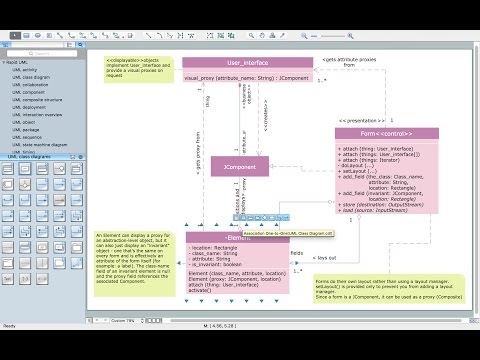
How to Make a UML Diagram in ConceptDraw PRO

HelpDesk
How to Create a Business Process Diagram

MS Visio Look a Like Diagrams

Business Process Flowchart Symbols

Process Flowchart


How to create a UML Diagram

How to Build a Flowchart

Swim Lane Flowchart Symbols

- Mouse Resize Pointer
- Keyboard Shortcuts and Mouse Actions | Mouse & Clicks | Computer ...
- iPhone OS (iOS) graphic user interface (GUI) - Activity indicator view ...
- Interactions - Vector stencils library | Interactions - Vector stencils ...
- iPhone OS (iOS) graphic user interface (GUI) - Activity indicator view ...
- Keyboard Shortcuts and Mouse Actions | Computer network - Vector ...
- Graphical User Interface Examples | Windows 10 User Interface ...
- Mouse Vector Png
- Design elements - Computer pictograms | Design Pictorial ...
- Window elements - Vector stencils library | Network Icon | Network ...