HelpDesk
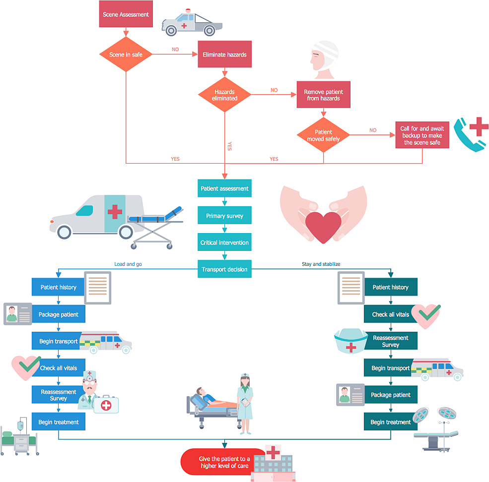
How to Create a Healthcare Management Workflow Diagram
Types of Flowcharts


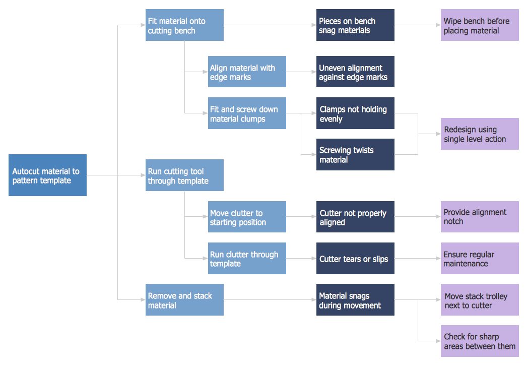
PDPC
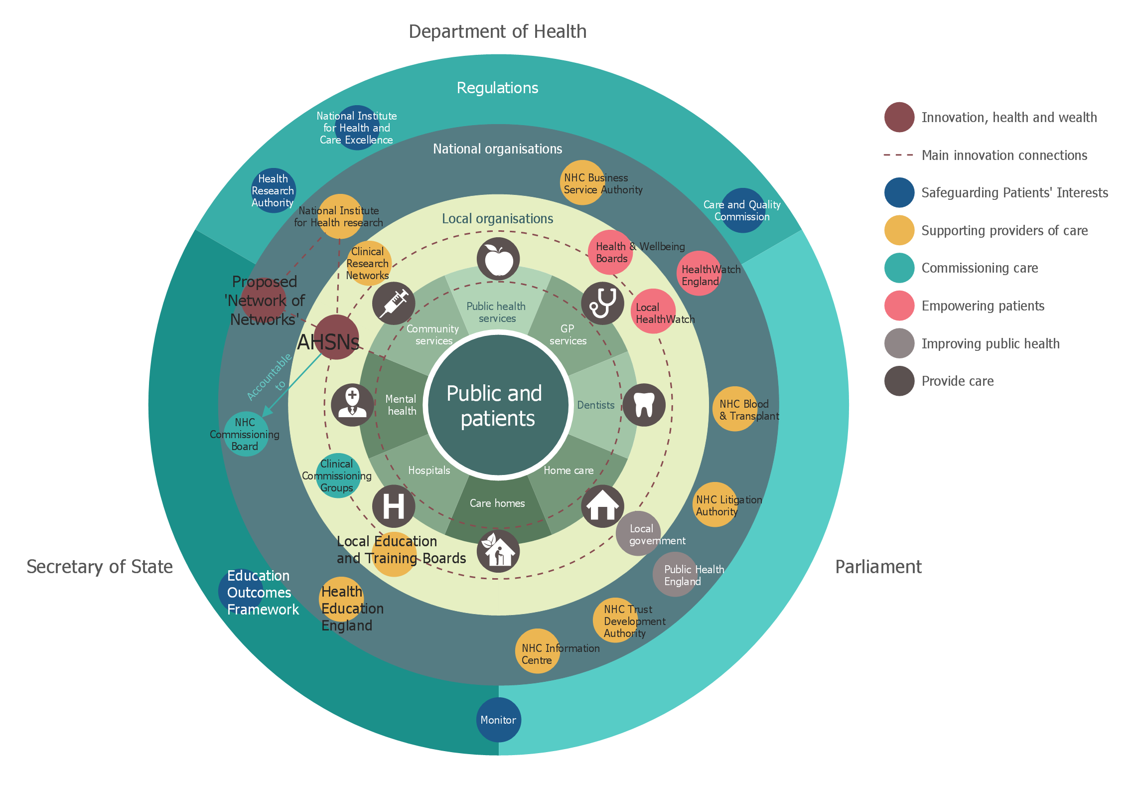
Stakeholder Onion Diagrams
UML Sample Project

Basic Flowchart Symbols and Meaning


Developing Entity Relationship Diagrams

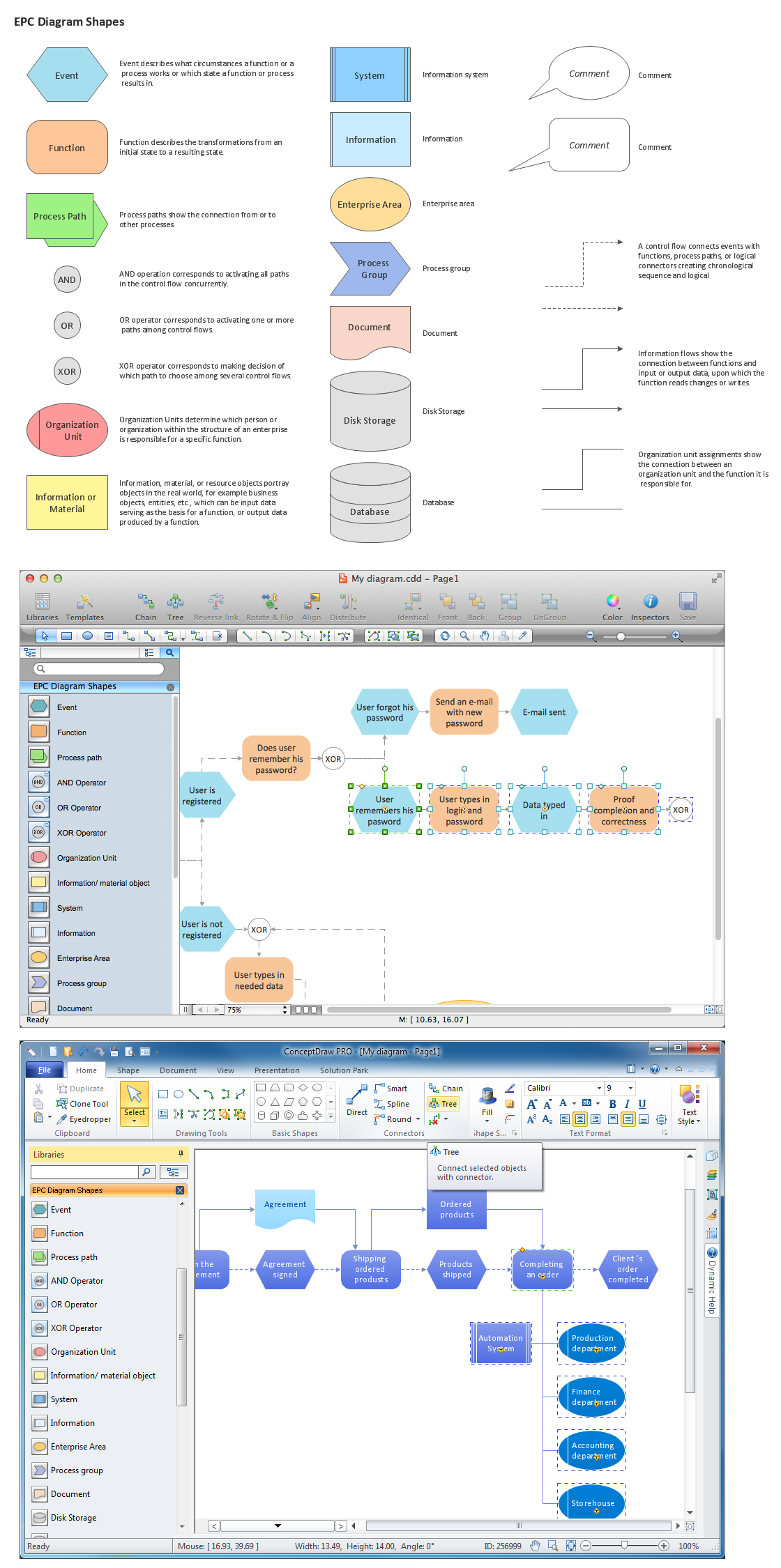
Graphical Symbols to use in EPC diagrams
Biomedical
UML Tool & UML Diagram Examples

- Healthcare Management Workflow Diagrams | Data Flow Diagram ...
- Data Flow Diagrams (DFD) | Healthcare Management Workflow ...
- Data Flow Diagram | Interaction Overview Diagram | Healthcare ...
- Healthcare Management Workflow Diagrams | IDEF0 Diagrams ...
- Process Flowchart | Block Diagrams | Context Diagram Template ...
- Context Diagram For An Hospital Example
- Context Level Diagram Of Hospital Management System Dfd
- Healthcare Management Workflow Diagrams | Line Graphs | How To ...
- Taxi Service Data Flow Diagram DFD Example | Accounting Data ...
- Context Diagram Of Medical Store Management System