HelpDesk
Downloading the Old Versions of ConceptDraw Products

ConceptDraw DIAGRAM Comparison with Omnigraffle Professional and MS Visio

HelpDesk
How to Create a Bank ATM Use Case Diagram

Use Case Diagrams technology with ConceptDraw DIAGRAM

Structured Systems Analysis and Design Method (SSADM) with ConceptDraw DIAGRAM

ConceptDraw Arrows10 Technology

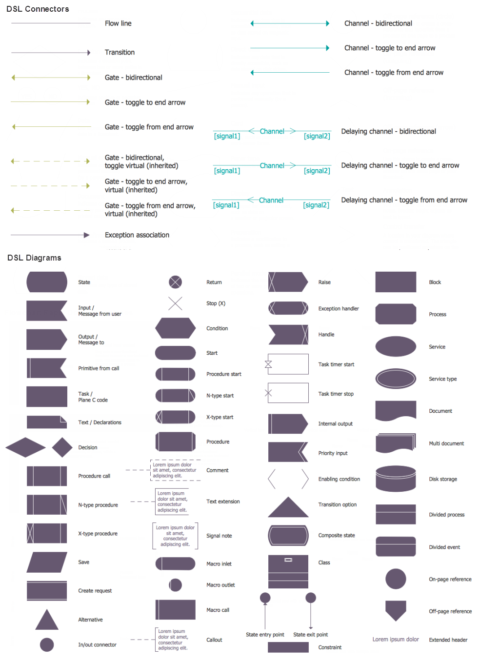
 SYSML
SYSML
The SysML solution helps to present diagrams using Systems Modeling Language; a perfect tool for system engineering.
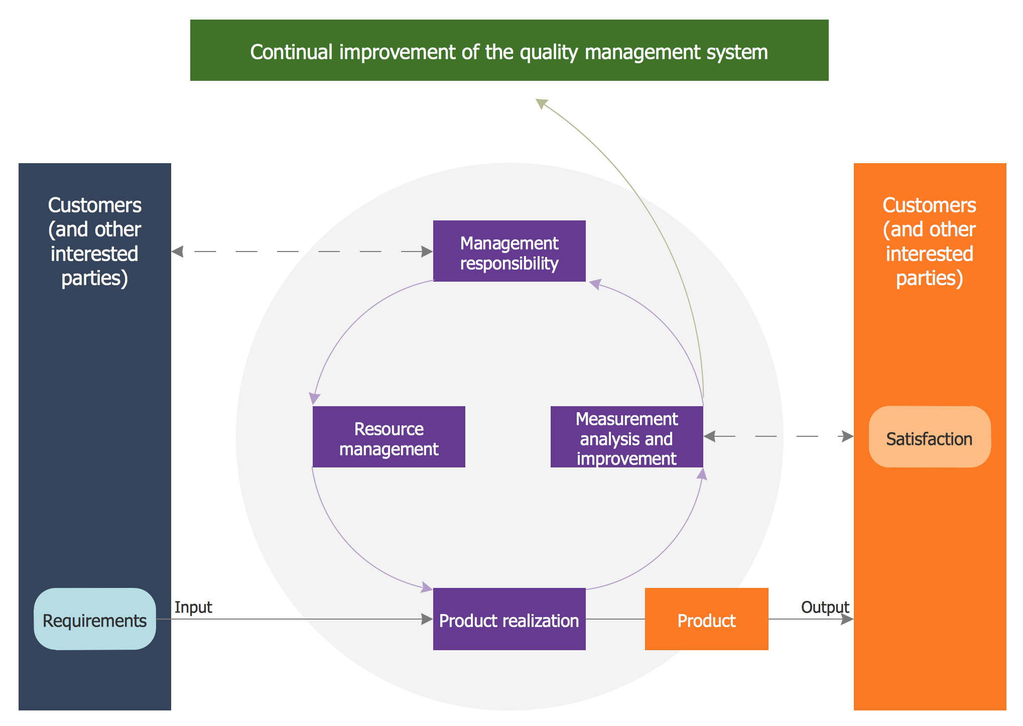
Quality Management System
System Design
 Website Wireframe
The innovative Website Wireframe solution enhances the ConceptDraw DIAGRAM functionality with newest wireframe tools, libraries with variety of predesigned icons, symbols, buttons, graphics, forms, boxes, and many other vector elements, templates and professionally designed samples, which make it the best wireframing software. Website Wireframe solution gives you significant advantages when designing and maintaining websites, creating skeletal and content-free depictions of website structure, making website prototypes and planning the content arrangement before committing to design, also speeds up the processes of sketching, producing and sharing wireframe examples of website style and interface design.
UML Flowchart Symbols

 Rapid UML
Rapid UML solution extends ConceptDraw DIAGRAM software with templates, samples and libraries of vector stencils for quick drawing the UML diagrams using Rapid Draw technology.
Software development with ConceptDraw DIAGRAM

IDEF9 Standard

- ConceptDraw PRO 9 Comparison with Omnigraffle Professional and ...
- Conceptdraw .com: Mind Map Software, Drawing Tools | Project ...
- Use Case Diagrams technology with ConceptDraw PRO | Financial ...
- How to Draw a Circular Arrows Diagram Using ConceptDraw PRO ...
- System Requirement Cycle Diagram Of Cab Management System
- Use Case Diagrams technology with ConceptDraw PRO ...
- ConceptDraw PRO 9 Comparison with Omnigraffle Professional and ...
- UML use case diagram - Banking system
- Use Case Diagrams technology with ConceptDraw PRO | UML Use ...
- Use Case Diagrams technology with ConceptDraw PRO | Cross ...
- UML Diagram of Parking | Use Case Diagrams technology with ...
- Use Case Diagrams technology with ConceptDraw PRO | UML Use ...
- Use Case Diagrams technology with ConceptDraw PRO | Campus ...
- Use Case Diagrams technology with ConceptDraw PRO | Drawing ...
- UML Use Case Diagram Example Registration System
- How To Make a Bubble Chart | Bubble diagrams with ConceptDraw ...
- Use Case Diagrams technology with ConceptDraw PRO | Basic ...
- Use Case Diagrams technology with ConceptDraw PRO | Scrum ...
- UML Diagrams with ConceptDraw PRO | Audio, Video, Media ...