Yourdon and Coad Diagram
The vector stencils library Yourdon and Coad Notation from the solution OOAD contains specific symbols of the Yourdon and Coad notation such as data store symbol, data process symbol, loop symbol for ConceptDraw DIAGRAM diagramming and vector drawing software. The OOAD solution is contained in the Software Development area of ConceptDraw Solution Park.OOSE Method
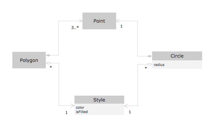
This sample shows the OOSE diagram with aggregation and composition associations. Using the Rapid UML Solution for ConceptDraw DIAGRAM you can create your own professional OOSE Diagrams quick and easy.Design Element: Crows Foot for Entity Relationship Diagram - ERD
Entity-Relationship Diagram (ERD) is ideal tool that helps execute the detalization of data warehouse for a given designed system, lets to document the system's entities, attributes (objects' properties), and their interactions each other (relationships). Creation of an ERD requires the choice of specific set of notations, which the best suits for your database design. Two notations - Chen’s and Crow's Foot are applied for ERDs design. Chen's notation was developed first and has linguistic approach, the boxes represent the entities and are considered as nouns, relationships between them are shown as diamonds in a verb form. Over time Chen’s style was adapted into the popular standard - Crow’s Foot notation, where entities are shown as boxes and relationships - as labeled lines. ConceptDraw DIAGRAM software supplied with Entity-Relationship Diagram (ERD) solution offers samples and templates of ER diagrams, and also ready-to-use vector design elements - ERD Crow′s Foot and Chen's notation icons for easy designing your own ER diagrams for depicting databases.IDEF0 Diagram
The vector stencils library IDEF0 Diagram from the solution IDEF0 Diagrams contains specific IDEF0 diagram symbols such as arrow symbols and entity symbols for ConceptDraw DIAGRAM diagramming and vector drawing software. The IDEF0 Diagram solution is contained in the Software Development area of ConceptDraw Solution Park.JSD - Jackson system development
Jackson System Development (JSD) is a linear method of system development created by Michael A. Jackson and John Cameron in the 1980s. It comprises the whole software life cycle directly or providing a framework for more specialized techniques. When implementing the Jackson System Development method and designing JSD diagrams, you can succesfully use the powerful and helpful tools of ConceptDraw DIAGRAM software extended with Entity-Relationship Diagram (ERD) solution from the Software Development area of ConceptDraw Solution Park.Software Diagram Examples and Templates
ConceptDraw DIAGRAM is a powerful tool for business and technical diagramming. Software Development area of ConceptDraw Solution Park provides 5 solutions: Data Flow Diagrams, Entity-Relationship Diagram (ERD), Graphic User Interface, IDEFO Diagrams, Rapid UML.UML Class Diagram. Design Elements
UML Class Diagrams describes the structure of a system by showing the system's classes, their attributes, and the relationships among the classes.- Coad / Yourdon's Object-Oriented Analysis model | Cross-Functional ...
- Data Flow Diagrams (DFD) | Coad Yourdon Methodology Ppt
- Yourdon and Coad Diagram | OOSE Method | Professionally ...
- Yourdon and Coad Diagram | Coad / Yourdon's Object-Oriented ...
- Data Flow Diagrams (DFD) | Coad Yourdon Method Ppt
- Booch OOD Diagram | OOSE Method | UML Flowchart Symbols ...
- Yourdon and Coad Diagram | OOSE Method | Coad / Yourdon's ...
- Booch OOD Diagram | Yourdon and Coad Diagram | Software ...
- Booch Methodology Ppt
- Structured Systems Analysis and Design Method (SSADM) with ...
- Jacobson Method In Ooad
- Booch OOD Diagram | Examples for OOSE Method | Object-Oriented ...
- Structured Systems Analysis and Design Method . SSADM with ...
- Yourdon and Coad Diagram | Data Flow Diagram Symbols. DFD ...
- Object-Oriented Design | Booch OOD Diagram | Coad / Yourdon's ...
- Booch OOD Diagram | Yourdon and Coad Diagram | Software ...
- Coad / Yourdon's Object-Oriented Analysis model | ConceptDraw ...
- Software development with ConceptDraw DIAGRAM | Methodology ...
- Agile Methodology | SSADM Diagram | Basic Flowchart Symbols ...
- Process Flowchart | Basic Flowchart Symbols and Meaning | Agile ...


