UML Class Diagram Notation

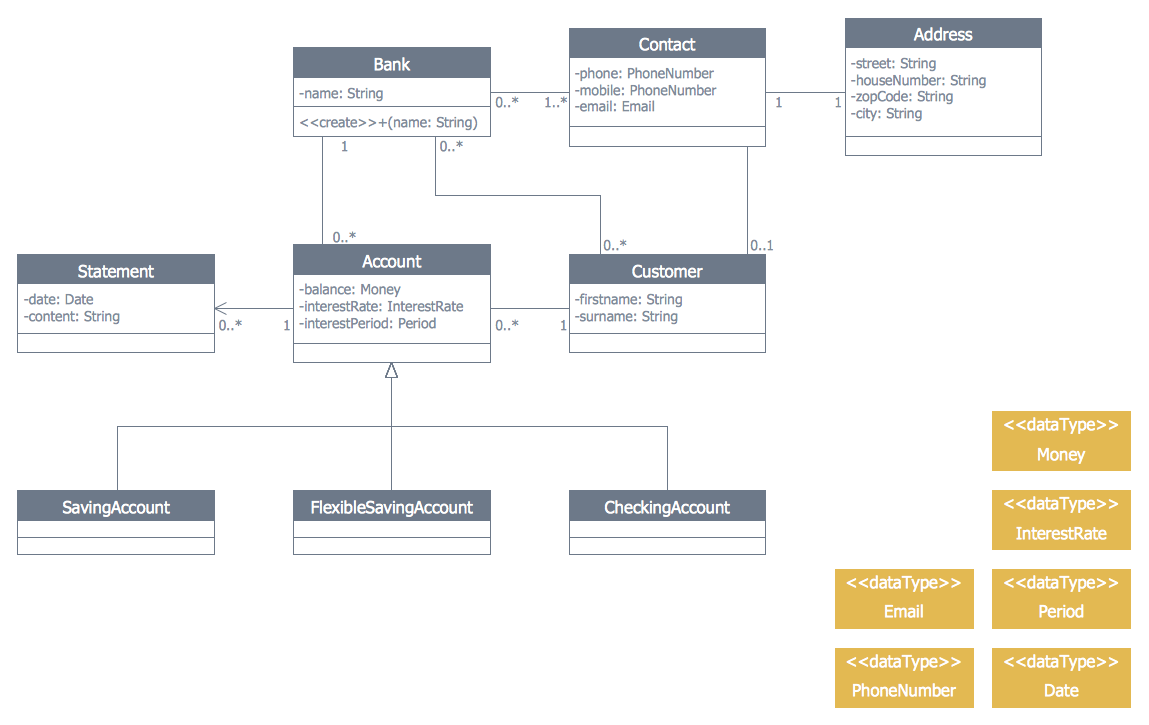
 ATM UML Diagrams
The ATM UML Diagrams solution lets you create ATM solutions and UML examples. Use ConceptDraw DIAGRAM as a UML diagram creator to visualize a banking system.
Software Diagram Examples and Templates

UML Class Diagram Example - Medical Shop

Entity Relationship Diagram Symbols

UML Block Diagram

UML Diagram

UML Diagram Editor
Examples for OOSE Method

Banking System
- Internet solutions with ConceptDraw PRO | Internet Logo Visio
- School and Training Plans | Computer Network Diagrams | Wireless ...
- UML Class Diagram Example for GoodsTransportation System ...
- Swim Lane Diagrams | Swim Lane Flowchart Symbols | Cross ...
- UML Class Diagram Example for Transport System | PM Docs | Data ...
- Swim Lane Diagrams | Types of Flowcharts | Business Process ...
- Diagrams Of Hospital Laboratory Equipment And Names
- UML Class Diagram Example for Transport System | UML Class ...
- Conceptdraw Software Logo
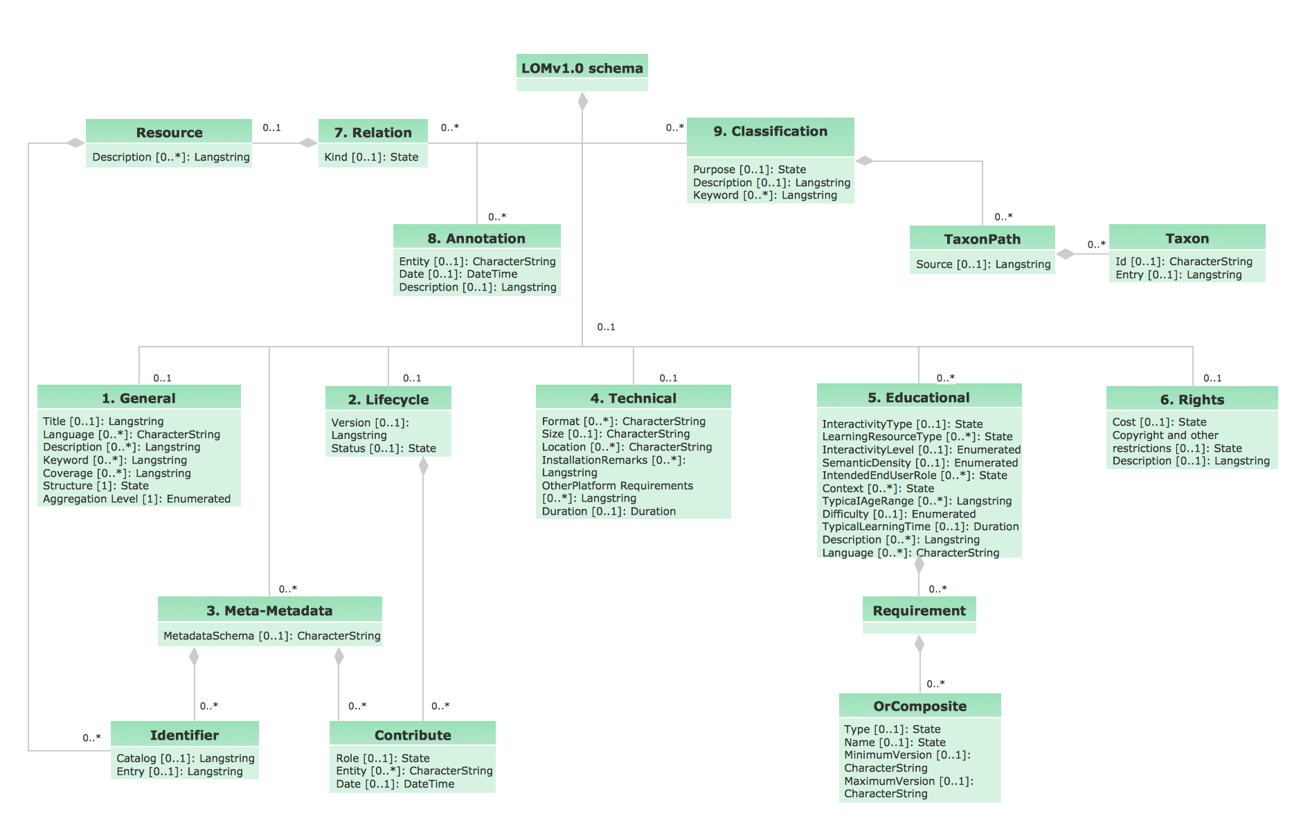
- UML class diagram - Metadata information model | AWS Application ...