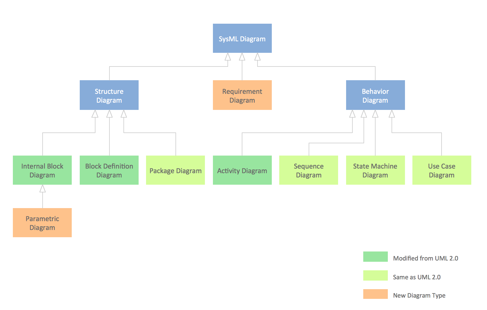
SysML Diagram
UML Use Case Diagram Example - Taxi Service

UML Use Case Diagram. Design Elements


Cisco IBM. Cisco icons, shapes, stencils and symbols

Fire Exit Plan. Building Plan Examples

Entity Relationship Diagram Software for Mac

 Computer Network Diagrams
Computer Network Diagrams solution extends ConceptDraw DIAGRAM software with samples, templates and libraries of vector icons and objects of computer network devices and network components to help you create professional-looking Computer Network Diagrams, to plan simple home networks and complex computer network configurations for large buildings, to represent their schemes in a comprehensible graphical view, to document computer networks configurations, to depict the interactions between network's components, the used protocols and topologies, to represent physical and logical network structures, to compare visually different topologies and to depict their combinations, to represent in details the network structure with help of schemes, to study and analyze the network configurations, to communicate effectively to engineers, stakeholders and end-users, to track network working and troubleshoot, if necessary.
 AWS Architecture Diagrams
AWS Architecture Diagrams with powerful drawing tools and numerous predesigned Amazon icons and AWS simple icons is the best for creation the AWS Architecture Diagrams, describing the use of Amazon Web Services or Amazon Cloud Services, their application for development and implementation the systems running on the AWS infrastructure. The multifarious samples give you the good understanding of AWS platform, its structure, services, resources and features, wide opportunities, advantages and benefits from their use; solution’s templates are essential and helpful when designing, description and implementing the AWS infrastructure-based systems. Use them in technical documentation, advertising and marketing materials, in specifications, presentation slides, whitepapers, datasheets, posters, etc.
 Stakeholder Onion Diagrams
The Stakeholder Onion Diagram is often used as a way to view the relationships of stakeholders to a project goal. A basic Onion Diagram contains a rich information. It shows significance of stakeholders that will have has influence to the success achieve
- Class Diagram For Hotel Management System
- Activity Diagram For Airport Management System Made In Microsoft
- SysML Diagram | UML Class Diagram Generalization Example UML ...
- Activity Diagram For Cab Management System
- SysML Diagram | UML Class Diagram Generalization Example UML ...
- Coceptual Class Diagram For Tourism Management Sysytem
- Class Diagram For Supermarket Management System Pdf
- Data Flow Diagram For Airport Management System
- UML Activity Diagram | ATM UML Diagrams | Usecase Diagram For ...