Electrical Symbols, Electrical Diagram Symbols

Wiring Diagrams with ConceptDraw DIAGRAM

Electrical Drawing Software and Electrical Symbols

Electrical Symbols — Transmission Paths
Electrical Symbols — Switches and Relays

Electrical Symbols — Analog and Digital Logic

The vector stencils library "Transmission paths" contains 43 symbols of power transmission paths, electronic circuits, bus connectors and elbows, terminals, junctions, and concentrators.
Use it to annotate electrical diagrams, electronic schematics and circuit diagrams in the ConceptDraw PRO diagramming and vector drawing software extended with the Electrical Engineering solution from the Engineering area of ConceptDraw Solution Park.
www.conceptdraw.com/ solution-park/ engineering-electrical
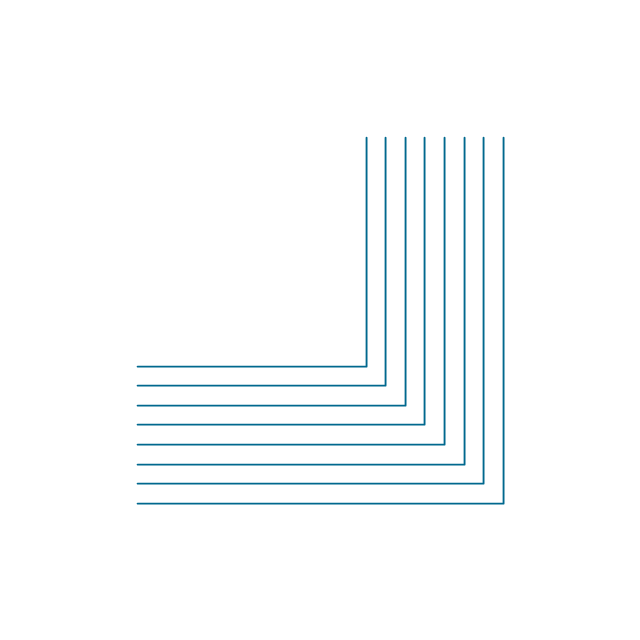
2-line bus

3-line bus 2

4-line bus

8-line bus

2-line bus elbow

3-line bus elbow 2

4-line bus elbow

8-line bus elbow

3-line bus

3-line bus elbow

4-line bus 2

8-line bus 2

4-line bus elbow 2

8-line bus elbow 2
Point

Terminal

Terminal 3-phase

Label

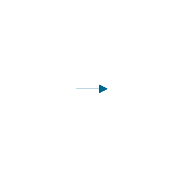
Flow direction, right
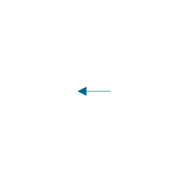
Flow direction, left
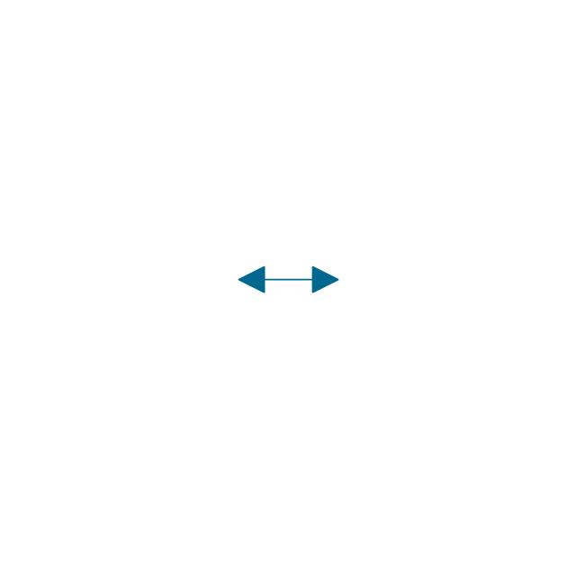
Flow direction, inward

Flow direction, outward
Transmission path

Line, overhead

Line, underground

Line, submarine

Line, loaded

Line, coaxial

Cable group

Lead group

Anticreep device

Line concentrator

Overground enclosure

Overground enclosure 2

Optical fiber

Optical fiber 2

Straight bus
Straight bus 2

Elbow bus

Elbow bus 2

Elbow bus 3

Elbow bus 4

Bus width
Electrical Engineering

Electrical Symbols — Composite Assemblies

Network Glossary Definition


- Network wiring cable. Computer and Network Examples | Basic ...
- Draw The Diagram Layout Cable Coaxial
- Connections Of Conductor Symbols For Engineering Drawing
- Design elements - Terminals and connectors | Terminals and ...
- Coaxial Cable Schematic Symbol
- Cable TV - Vector stencils library | Hardware - Vector stencils library ...
- IDEF3 Standard | Network Diagrams for Bandwidth Management ...
- Terminals and connectors - Vector stencils library | Design elements ...
- Buses Circuit Images
- Optical Fiber Connection Line Diagram Tools