Export from ConceptDraw PRO Document to a Graphic File


 Chemical and Process Engineering
This chemical engineering solution extends ConceptDraw PRO v.9.5 (or later) with process flow diagram symbols, samples, process diagrams templates and libraries of design elements for creating process and instrumentation diagrams, block flow diagrams (BFD
Geo Map - Asia - Papua New Guinea

HelpDesk
How to Draw a Chemical Process Flow Diagram

Emergency Plan


Pyramid Diagram

This process flow diagram (PFD) example shows an amine treating system for the removal of gaseous hydrogen sulfide from gas streams. It is used in oil refineries and chemical plants. This PFD sample was redesigned from the Wikimedia Commons file: AmineTreating.png. [commons.wikimedia.org/ wiki/ File:AmineTreating.png]
This file is licensed under the Creative Commons Attribution-Share Alike 3.0 Unported license. [creativecommons.org/ licenses/ by-sa/ 3.0/ deed.en]
"Amine gas treating, also known as gas sweetening and acid gas removal, refers to a group of processes that use aqueous solutions of various alkylamines (commonly referred to simply as amines) to remove hydrogen sulfide (H2S) and carbon dioxide (CO2) from gases. It is a common unit process used in refineries, and is also used in petrochemical plants, natural gas processing plants and other industries.
Processes within oil refineries or chemical processing plants that remove hydrogen sulfide are referred to as "sweetening" processes because the odor of the processed products is improved by the absence of hydrogen sulfide. An alternative to the use of amines involves membrane technology. Membranes are attractive since no reagents are consumed.
Many different amines are used in gas treating:
Diethanolamine (DEA),
Monoethanolamine (MEA),
Methyldiethanolamine (MDEA),
Diisopropanolamine (DIPA),
Aminoethoxyethanol (Diglycolamine) (DGA).
The most commonly used amines in industrial plants are the alkanolamines DEA, MEA, and MDEA. These amines are also used in many oil refineries to remove sour gases from liquid hydrocarbons such as liquified petroleum gas (LPG)." [Amine gas treating. Wikipedia]
The PFD example "Amine treating unit schematic diagram" was drawn using the ConceptDraw PRO diagramming and vector drawing software extended with the Chemical and Process Engineering solution from the Chemical and Process Engineering area of ConceptDraw Solution Park.
Process Flow Diagram (PFD)
-amine-treating-unit-schematic-diagram.png--diagram-flowchart-example.png)
Cause and Effect Diagram

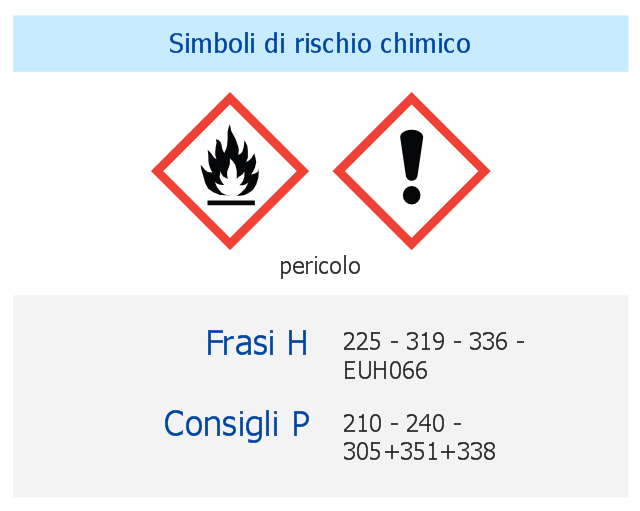
This italian chemical safety infographic example shows the ethyl acetate infobox including 3 sections: GHS hazard pictograms, Hazard statements and Precautionary statements.
It was designed on the base of the table from the Wikimedia Commons file: Consigli P.png. [commons.wikimedia.org/ wiki/ File:Consigli_ P.png]
"Ethyl acetate is the organic compound with the formula CH3–COO–CH2–CH3. This colorless liquid has a characteristic sweet smell (similar to pear drops) and is used in glues, nail polish removers, decaffeinating tea and coffee, and cigarettes (see list of additives in cigarettes). Ethyl acetate is the ester of ethanol and acetic acid; it is manufactured on a large scale for use as a solvent." [Ethyl acetate. Wikipedia]
The chemical safety infographic sample "Acetato di etile" was created using ConceptDraw PRO software extended with the GHS Hazard Pictograms solution from the Engineering area of ConceptDraw Solution Park.
Chemical safety infographic
Chemical Engineering

- Hazard Chemical Sign | Chemical Engineering | Transport Hazard ...
- Chemical Vector Png
- Natural Element Symbol Png
- Design elements - Periodic table of chemical elements | Design ...
- Health Food | Chemical elements - Vector stencils library | Calcium ...
- Plumbing and Piping Plans | Landscape & Garden | Chemical and ...
- Process Flow Diagram Symbols | Chemical Engineering | Chemical ...
- HVAC control equipment - Vector stencils library | Chemical ...
- Flammable Symbol Png
- Chemical elements - Vector stencils library | Design elements - ERD ...