Electrical Symbols — Terminals and Connectors

The vector stencils library "Terminals and connectors" contains 43 element symbols of terminals, connectors, plugs, polarized connectors, jacks, coaxial cables, and conductors.
Use it for drawing the wiring diagrams, electrical layouts, electronic schematics, and circuit diagrams.
"An electrical connector is an electro-mechanical device for joining electrical circuits as an interface using a mechanical assembly. Connectors consist of plugs (male-ended) and jacks (female-ended). The connection may be temporary, as for portable equipment, require a tool for assembly and removal, or serve as a permanent electrical joint between two wires or devices. An adapter can be used to effectively bring together dissimilar connectors.
There are hundreds of types of electrical connectors. Connectors may join two lengths of flexible copper wire or cable, or connect a wire or cable or optical interface to an electrical terminal.
In computing, an electrical connector can also be known as a physical interface... Cable glands, known as cable connectors in the US, connect wires to devices mechanically rather than electrically and are distinct from quick-disconnects performing the latter." [Electrical connector. Wikipedia]
"A terminal is the point at which a conductor from an electrical component, device or network comes to an end and provides a point of connection to external circuits. A terminal may simply be the end of a wire or it may be fitted with a connector or fastener. In network analysis, terminal means a point at which connections can be made to a network in theory and does not necessarily refer to any real physical object. In this context, especially in older documents, it is sometimes called a "pole".
The connection may be temporary, as seen in portable equipment, may require a tool for assembly and removal, or may be a permanent electrical joint between two wires or devices.
All electric cell have two terminals. The first is the positive terminal and the second is the negative terminal. The positive terminal looks like a metal cap and the negative terminal looks like a metal disc. The current flows from the positive terminal, and out through the negative terminal, replicative of current flow (positive (+) to negative (-) flow)." [Terminal (electronics). Wikipedia]
The shapes example "Design elements - Terminals and connectors" was drawn using the ConceptDraw PRO diagramming and vector drawing software extended with the Electrical Engineering solution from the Engineering area of ConceptDraw Solution Park.
Terminal and connector symbols

The vector stencils library "Terminals and connectors" contains 43 element symbols of terminals, connectors, plugs, polarized connectors, jacks, coaxial cables, and conductors.
Use it for drawing the wiring diagrams, electrical layouts, electronic schematics, and circuit diagrams in the ConceptDraw PRO diagramming and vector drawing software extended with the Electrical Engineering solution from the Engineering area of ConceptDraw Solution Park.
www.conceptdraw.com/ solution-park/ engineering-electrical
2-conductor jack

2-conductor plug

2-conductor jack 2

2-conductor plug 2

Normalled jacks

Normalled jack

Outside conductor coaxial

Center conductor coaxial

Large D connector

Small D connector

C header connector

Normalled jacks

Сontact, male

Сontact, female

Сontact, male 2

Сontact, female 2

Adapter, male - male

Adapter, male - male

Circuit terminal

Terminal board

Cable termination, complete

Cable termination, single-line

Cable termination, single-line 2

Shielded jack

Shielded plug

Coaxial jack

Coaxial plug

2-conductor, male

2-conductor, female

2-conductor, male 2

2-conductor, female 2

2-conductor, male 3

2-conductor, female 3

3-conductor, male

3-conductor, female

3-conductor, male 2

3-conductor, female 2

3-conductor, male 3

3-conductor, female 3

3-conductor, male 4

3-conductor, female 4

3-conductor, male 5

3-conductor, female 5

Electrical Symbols, Electrical Diagram Symbols

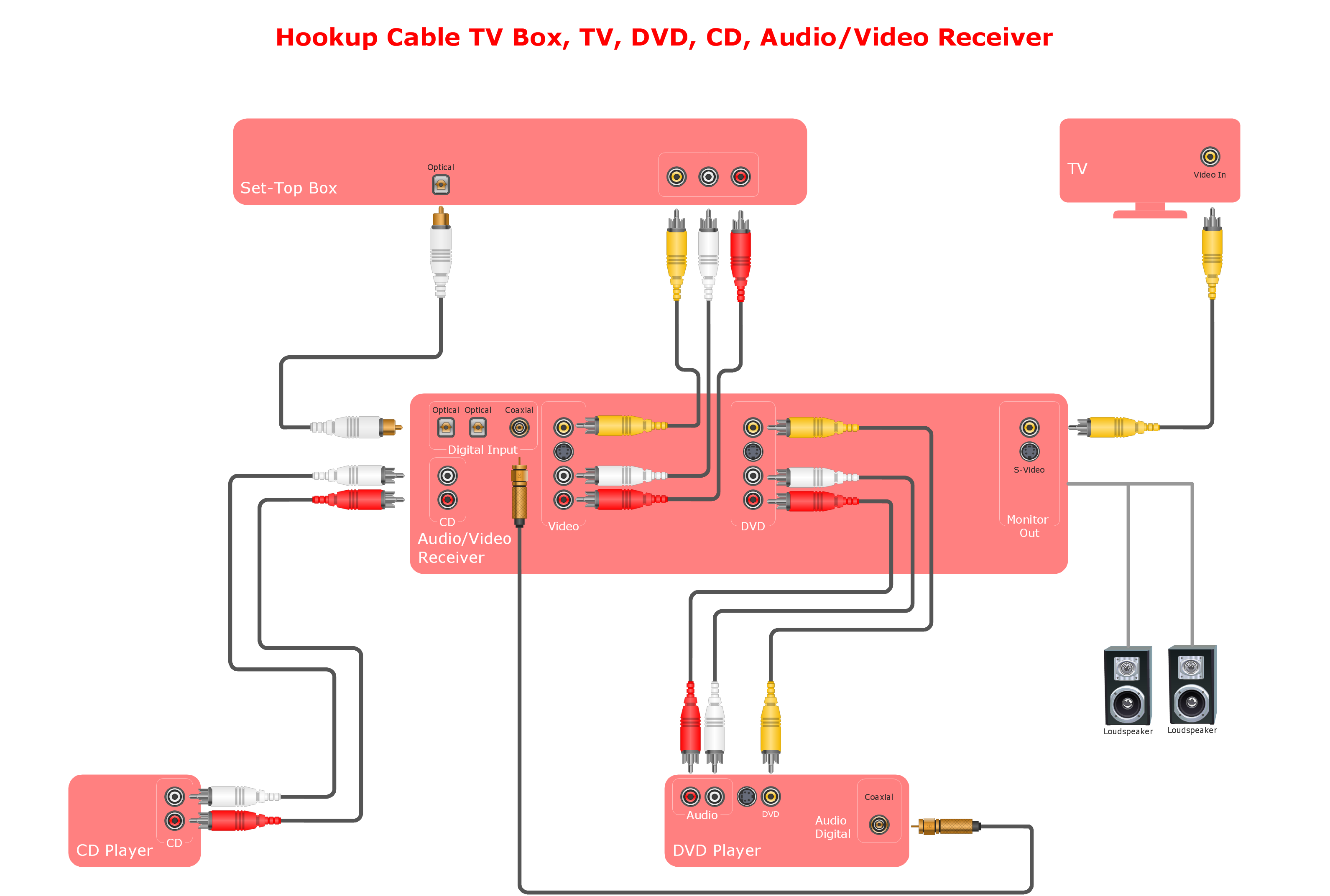
Standard Universal Audio & Video Connection Types

Electrical Drawing Software and Electrical Symbols

The vector stencils library "Audio and video connectors" contains 94 symbols of audio and video connectors and device silhouettes.
Use these jacks and plugs clipart icons for drawing hook up diagrams in the ConceptDraw PRO diagramming and vector drawing software extended with the Audio and Video Connectors solution from the Engineering area of ConceptDraw Solution Park.
www.conceptdraw.com/ solution-park/ engineering-audio-video-connectors
Device 1

Device 2

TV

Cable, thin

Cable, thick

Device 1, half part

Device 2, half part

TRS plug, purple
TRS plug, brown
TRS plug, black

TRS plug, gray
TRS plug, blue
TRS plug, green
TRS jack, purple

TRS jack, brown

TRS jack, black

TRS jack, gray

TRS jack, blue

TRS jack, green

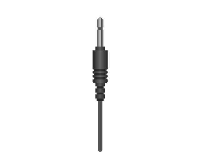
TRS plug, micro-jack
TRS, micro-jack

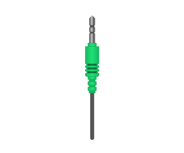
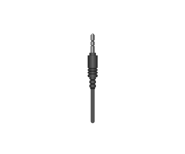
Headphone Mini Jack Cable
Headphone Mini Jack

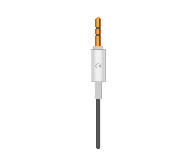
Microphone Mini Jack Cable
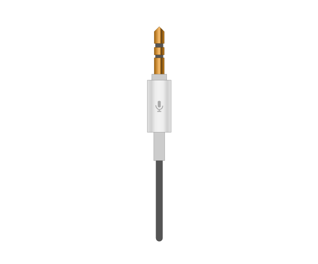
Microphone Mini Jack

XLR female Neutrik
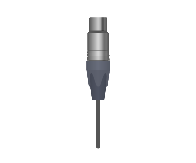
XLR female Neutrik

TOSLINK Optical Audio Cable, blue
TOSLINK Optical Audio Cable
TOSLINK Optical jack
TOSLINK Optical jack, blue

DVI plug
DVI-I (Single Link) jack
-jack-audio-and-video-connectors---vector-stencils-library.png--diagram-flowchart-example.png)
DVI-I (Dual Link) jack
-jack-audio-and-video-connectors---vector-stencils-library.png--diagram-flowchart-example.png)
DVI-D (Single Link) jack
-jack-audio-and-video-connectors---vector-stencils-library.png--diagram-flowchart-example.png)
DVI-D (Dual Link) jack
-jack-audio-and-video-connectors---vector-stencils-library.png--diagram-flowchart-example.png)
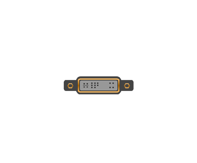
DVI-A Port
DVI-I (Single Link)
-audio-and-video-connectors---vector-stencils-library.png--diagram-flowchart-example.png)
DVI-I (Dual Link)
-audio-and-video-connectors---vector-stencils-library.png--diagram-flowchart-example.png)
DVI-D (Single Link)
-audio-and-video-connectors---vector-stencils-library.png--diagram-flowchart-example.png)
DVI-D (Dual Link)
-audio-and-video-connectors---vector-stencils-library.png--diagram-flowchart-example.png)
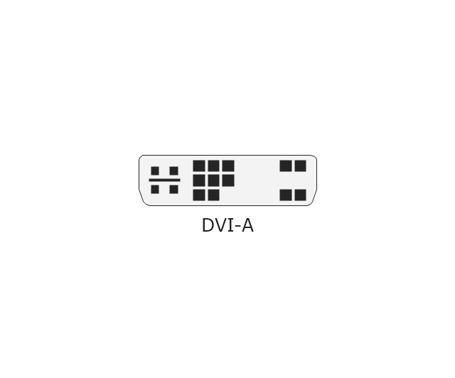
DVI-A
Mini DVI jack
Mini DVI plug
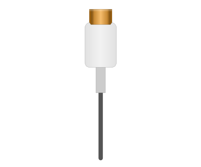
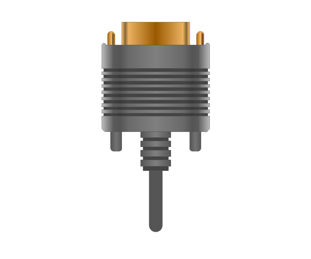
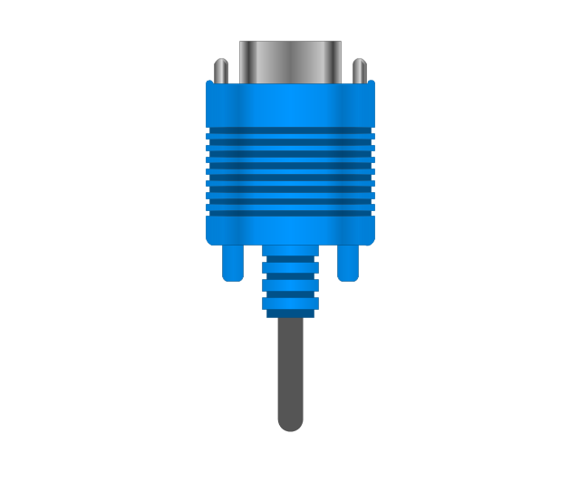
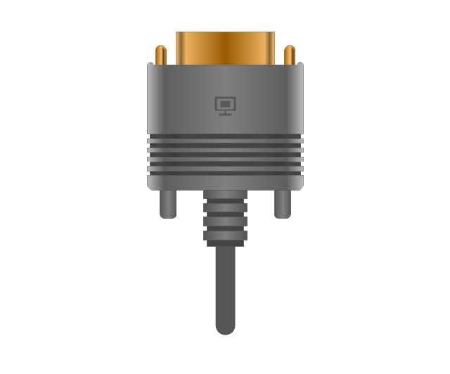
VGA plug
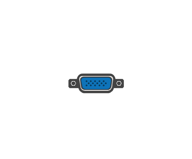
VGA jack
DFP jack
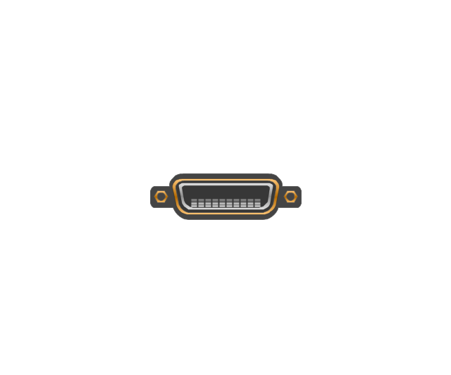
DFP plug
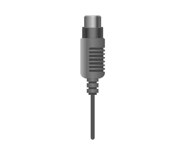
S-Video plug
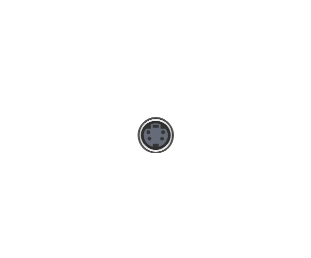
S-Video IN

S-Video OUT
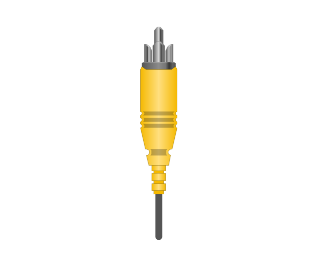
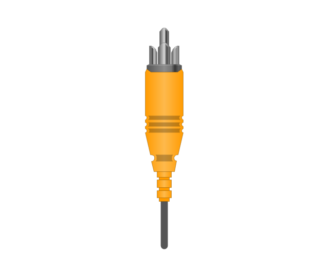
RCA, yellow

RCA, yellow
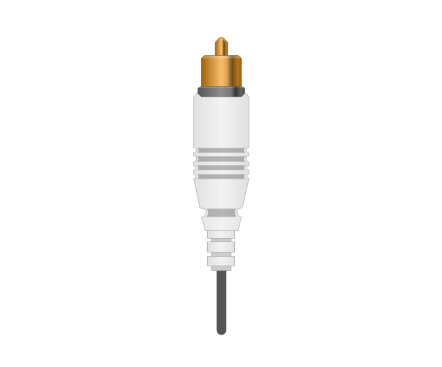
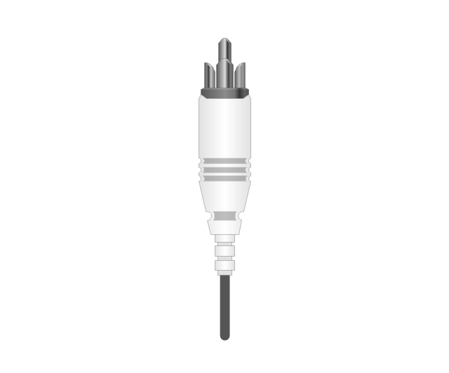
RCA, white

RCA, white
RCA, red

RCA, red

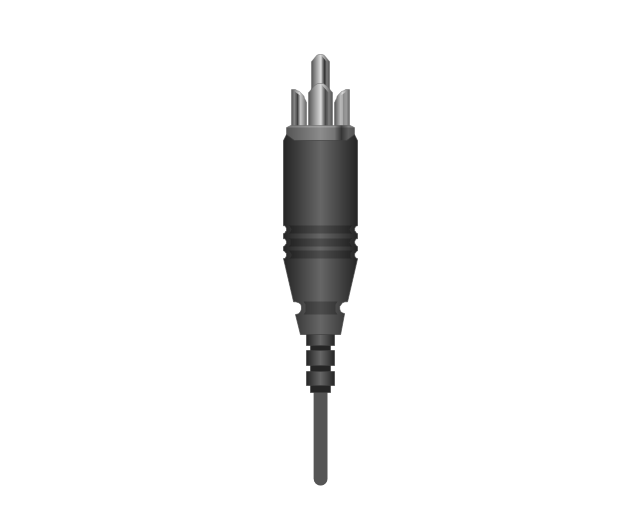
RCA, black

RCA, black
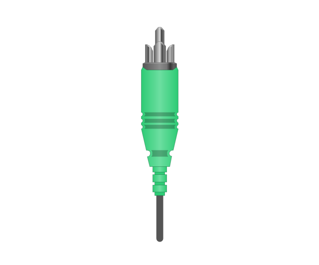
RCA, green

RCA, green
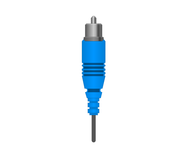
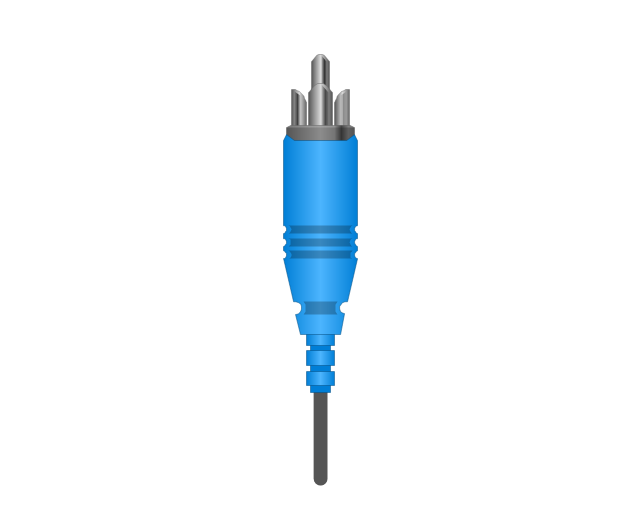
RCA, blue

RCA, blue
RCA, gray

RCA, gray
RCA, brown

RCA, brown
RCA, tan

RCA, tan
RCA, purple
RCA, purple

RCA, orange

RCA, orange
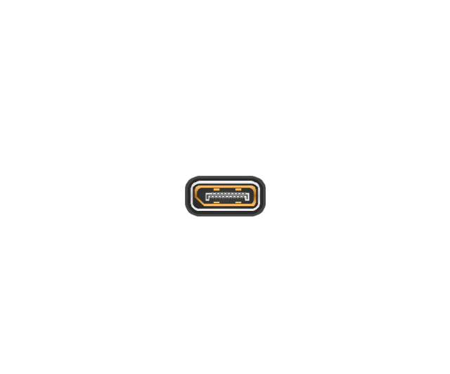
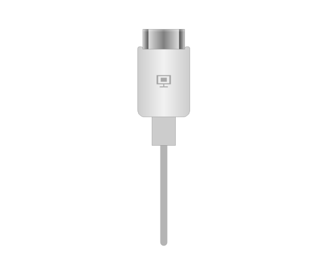
Display Port socket
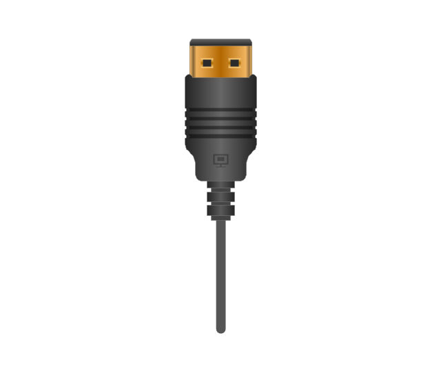
Display Port plug
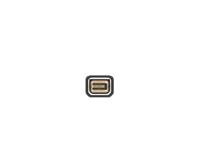
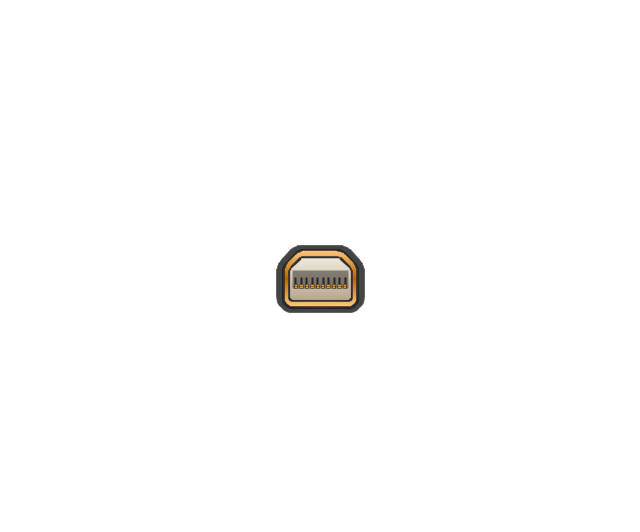
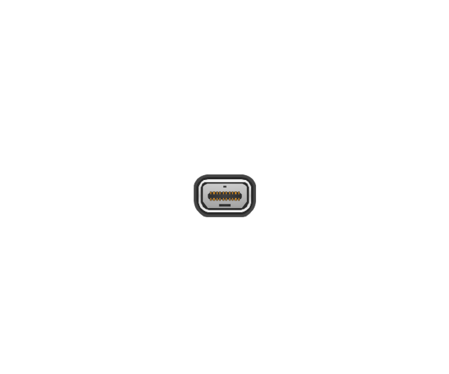
Mini Display port socket
Mini Display port socket, white

Mini Display port plug
Mini Display port plug, white
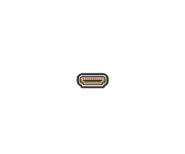
HDMI jack
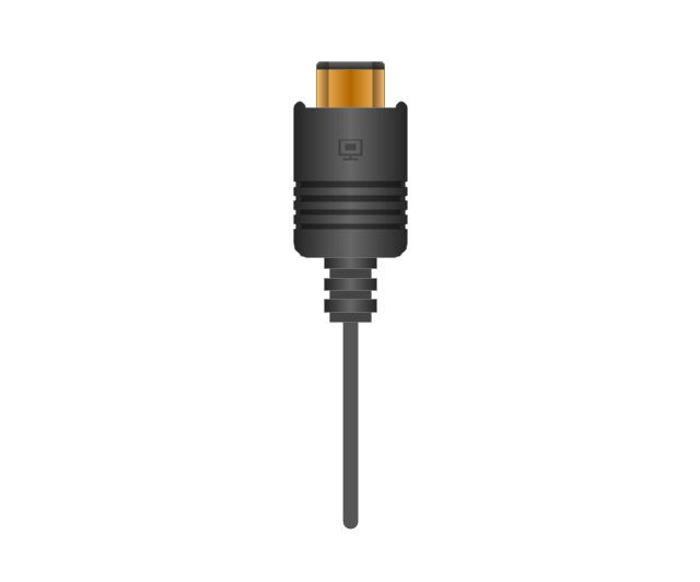
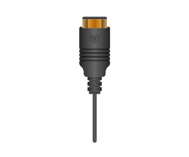
HDMI plug
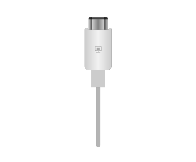
HDMI plug, white
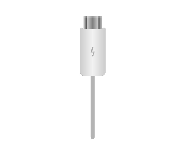
Thunderbolt jack
Thunderbolt plug
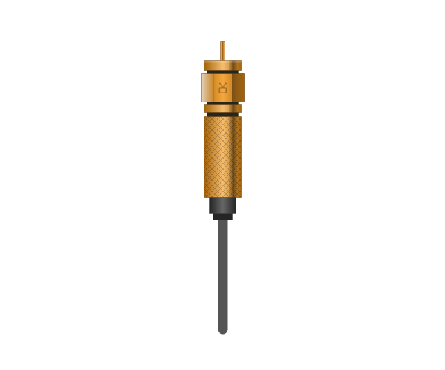
Coaxial TV plug
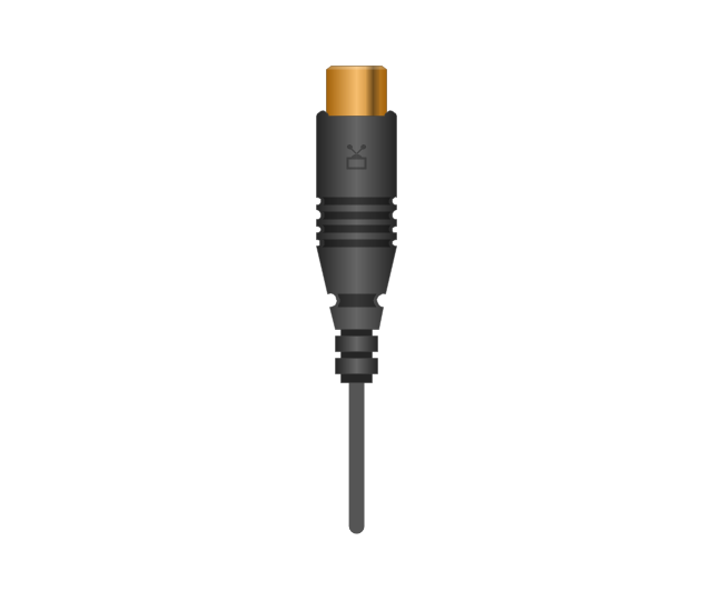
Coaxial TV jack

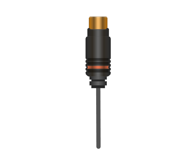
F connector jack

F connector plug
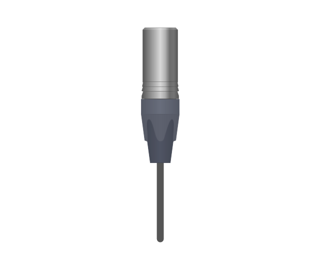
XLR male Neutrik

XLR male Neutrik
TS plug
TS jack

MIDI

MIDI
Network Glossary Definition


Audio and Video Connections Explained
ConceptDraw Arrows10 Technology

How to Make Audio and Video Connections

How To Print Audio & Video Connectors Schema in a Large Format
The vector stencils library "Video and audio" contains 50 symbols of devices and equipment.
Use it for drawing audio and video system layouts, cabling floor plans, electrical circuit schematic and wiring diagrams in the ConceptDraw PRO diagramming and vector drawing software.
The vector stencils library "Video and audio" is included in the Electric and Telecom Plans solution from the Building Plans area of ConceptDraw Solution Park.
Audio amplifier

RF amplifier

Video amplifier

Generic automatic switcher

Generic A/V switcher

Generic source component

System components

Headphone jack

Infrared receiver

Infrared transmitter

Music keypad

Mono speaker outlet

Stereo speaker outlet

Speaker ceiling

Speaker in-wall

Speaker subwoofer

Speaker weatherproof

Buzzer and bleeper

Piezo transducer

Microphone

Earphone

Cable antenna outlet

Master antenna outlet

Volume control

Volume control

Flush mounted intercom unit

Master intercom and directory unit

Floor mounted microphone outlet

Wall mounted microphone outlet

Ceiling mounted speaker

Speaker horn

Wall mounted speaker

Call in switch

Ceiling mounted paging speaker

Wall mounted paging speaker

Flush mounted data floor outlet

Flush mounted data floor outlet

Flush mounted data / telephone floor outlet

Surface mounted data floor outlet

Surface mounted data floor outlet

Surface mounted data / telephone floor outlet

Data outlet

Telephone outlet

Telephone, data outlet

Wall mounted telephone outlet

Equipment cabinet

Free standing equipment rack

Plywood backboard

Terminal cabinet with plywood backing

Wall mounted equipment rack

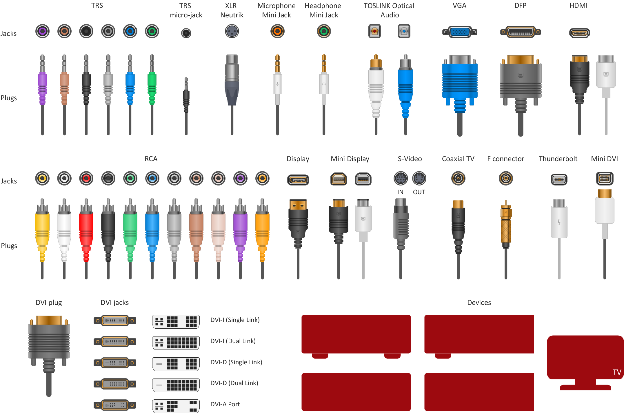
The vector stencils library "Audio and video connectors" contains 94 symbols of audio and video connectors (TRS, TS, XLR, microphone, headphone, TOSLINK, DVI, VGA, DFP, S-Video, RCA, display port, HDMI, Thunderbolt, coaxial TV, F connector, MIDI) and device silhouettes.
Use these jacks and plugs clipart icons for drawing hook up diagrams.
"Audio connectors and video connectors are electrical connectors (or optical connectors) for carrying audio signal and video signal, of either analog or digital format. Analog A/ V connectors often use shielded cables to inhibit radio frequency interference (RFI) and noise." [Audio and video connector. Wikipedia]
"The existence of many different audio and video standards necessitates the definition of hardware interfaces, which define the physical characteristics of the connections between electrical equipment. This includes the types and numbers of wires required along with the strength and frequency of the signal. It also includes the physical design of the plugs and sockets.
An interface may define a connector that is used only by that interface (e.g., DVI) or may define a connector that is also used by another interface; for example, RCA connectors are defined both by the composite video and component video interfaces.
Audio connectors and video connectors are electrical connectors (or optical connectors) for carrying audio signal and video signal, of either analog or digital format. Analog A/ V connectors often use shielded cables to inhibit radio frequency interference (RFI) and noise.
Since both analog and digital signals are used with some styles of connectors, knowledge of the interface used is necessary for a successful transfer of signals. Some interface types use only a distinctive connector or family of connectors, to ensure compatibility. Especially with analog interfaces, physically interchangeable connectors may not carry compatible signals.
Some of these connectors, and other types of connectors, are also used at radio frequency (RF) to connect a radio or television receiver to an antenna or to a cable system..." [Audio and video interfaces and connectors. Wikipedia]
The clipart icons example "Design elements - Audio and video connectors" was created using the ConceptDraw PRO diagramming and vector drawing software extended with the Audio and Video Connectors solution from the Engineering area of ConceptDraw Solution Park.
Audio and video jacks and plugs

This vector stencils library contains 195 cloud computing icons.
Use it to design cloud computing infographic and diagrams with ConceptDraw PRO software.
"Cloud computing, also on-demand computing, is a kind of Internet-based computing that provides shared processing resources and data to computers and other devices on demand. It is a model for enabling ubiquitous, on-demand access to a shared pool of configurable computing resources (e.g., networks, servers, storage, applications and services), which can be rapidly provisioned and released with minimal management effort. Cloud computing and storage solutions provide users and enterprises with various capabilities to store and process their data in third-party data centers.
Cloud computing has become a highly demanded service or utility due to the advantages of high computing power, cheap cost of services, high performance, scalability, accessibility as well as availability." [Cloud computing. Wikipedia]
The vector stencils library "Cloud clipart" is included in the Cloud Computing Diagrams solution from the Computer and Networks area of ConceptDraw Solution Park.
Access point
Airport

Alert

Banknote

Banknote bundle
Banknote bundles
Backup

Bar chart

Big data

Book (closed)
-cloud-clipart---vector-stencils-library.png--diagram-flowchart-example.png)
Book (open)
-cloud-clipart---vector-stencils-library.png--diagram-flowchart-example.png)
Books

Box, close

Box, open

Braces

Brackets

Bug

Building

Bus

Cable connection
Calculator
Calendar

Car

CD/DVD

Check list

Check mark

Clock
Cloud

Cloud computing
Cloud database

Cloud hosting
Cloud storage

Code
Coffee cup

Coin

Coins stack
Coins stacks
Communication

Computer terminal
Console

CPU
Credit card

Cubes
Dashboard

Database
Databases

Datacenter
Dialog box
Dialog boxes

Document

Documents

Dollar sign

Download

Earth

Email

Equal sign
Ethernet jack
Ethernet plug
Euro sign

Exclamation mark

Eye
Feed symbol

Feedback

File

Files

Filter

Firewall

Flash drive
Folder

Folders

Gamepad

Gauge

Gear

Gears, 2

Gears, 3

Globe

Hacker

Hard drive

Heart

Heart rhythm

Home

Hosting
Hotel

House

Image

Info

IP phone
Jet

Key

Keyboard
Laptop

Lego
Letter

Light bulb

Lightning
Line chart
Linux penguin

List

Load balancer
Location mark

Lock, close

Lock, open

Lock and key

Log
Login

Logout

Magnifying glass

Mail

Map

Memory (RAM)
-cloud-clipart---vector-stencils-library.png--diagram-flowchart-example.png)
Microphone

Minus sign
Mobile phone
Monitor

Mouse
Movie

Music

Music player

Network
Network bus

Newspaper

NIC (Network interface controller)
-cloud-clipart---vector-stencils-library.png--diagram-flowchart-example.png)
Not found (Error 404)
-cloud-clipart---vector-stencils-library.png--diagram-flowchart-example.png)
Notebook
Office printer
Operator

Page
Pages

PC

Pencil

Photo

Photo camera

Pie chart

Platform

Plus sign

Pound sign

Printer
Puzzle

Puzzles, 2x2

Puzzles, 3x3

Question sign

Rackmount server
Router
Safe
Satellite

Satellite antenna
Schedule

Sensor
Server

Server rack
Shield
Ship

Shopping bag

Shopping basket

Shopping cart

Sign up

Smartphone
Social network
Software box

Sound

Spider

Spreadsheet
SSD
Star

Stars, 5

Stethoscope

Stickman

Stickmen

Suitcase

Support
Switch
Syringe

Tablet computer
Tools

Train

Truck

Truck 2

TV

Umbrella
Upload

User man

User woman

User profile

Video
Video camera

Video mail

Virtual disk

Virus

Wallet

Web camera

Wifi antenna
Wireless
Wrench

X cross symbol

Yen sign

- Electrical Symbols , Electrical Diagram Symbols | Electrical Drawing ...
- Cable Gland Electrical Symbol
- Electrical Symbols For Plug
- Electrical Symbols — Terminals and Connectors | Cable TV - Vector ...
- Electrical Symbols — Terminals and Connectors | Cable TV - Vector ...
- Plug And Socket Male And Female Symbol
- Coaxial Cable Schematic Symbol
- Video and audio - Vector stencils library | Intercom Jack Dwg Symbol
- Coaxial Cable Symbol On Visio
- Jack Symbol
- Electrical Symbol For Rca Jack
- Electrical Symbols — Terminals and Connectors | How To use ...
- Design elements - Terminals and connectors | Electrical Symbols ...
- Jack Circuit Symbol
- Electrical Symbol Of Cable
- Electrical Symbols — Terminals and Connectors | How To use ...
- Electrical Plug Symbol
- Electrical Symbols — Terminals and Connectors | Design elements ...
- Well Labeled Diagram Of A Coaxial Cable Connector
- Network Cable Layout Plan