The vector stencils library "Network layout floorplan" contain 34 symbol icons for drawing computer network floor plans and communication equipment and cabling layouts.
"Networking hardware may also be known as network equipment or computer networking devices. Units which are the last receiver or generate data are called hosts or data terminal equipment.
All these terms refer to devices facilitating the use of a computer network. Specifically, they mediate data in a computer network. ...
Typically, networking hardware includes gateways, routers, network bridges, switches, hubs, and repeaters. But it also includes hybrid network devices such as multilayer switches, protocol converters, bridge routers, proxy servers, firewalls, network address translators, multiplexers, network interface controllers, wireless network interface controllers, modems, ISDN terminal adapters, line drivers, wireless access points, networking cables and other related hardware.
The most common kind of networking hardware today is a copper-based Ethernet adapter because of its standard inclusion on most modern computer systems. Wireless networking has, however, become increasingly popular, especially for portable and handheld devices.
Other hardware prevalent in computer networking includes data center equipment (such as file servers, database servers and storage areas), network services (such as DNS, DHCP, email, etc.) as well as devices which assure content delivery." [Networking hardware. Wikipedia]
The shapes example "Design elements - Network layout floorplan" was created using the ConceptDraw PRO diagramming and vector drawing software extended with the Network Layout Floor Plans solution from the Computer and Networks area of ConceptDraw Solution Park.
Network layout floor plan symbols

Cisco Network Design. Cisco icons, shapes, stencils, symbols and design elements

The vector stencils library "Cisco network topology" contains 89 symbols of Cisco network devices and design elements for drawing computer network topology diagrams.
"There are two basic categories of network topologies:
(1) Physical topologies,
(2) Logical topologies.
The shape of the cabling layout used to link devices is called the physical topology of the network. This refers to the layout of cabling, the locations of nodes, and the interconnections between the nodes and the cabling. The physical topology of a network is determined by the capabilities of the network access devices and media, the level of control or fault tolerance desired, and the cost associated with cabling or telecommunications circuits.
The logical topology in contrast, is the way that the signals act on the network media, or the way that the data passes through the network from one device to the next without regard to the physical interconnection of the devices." [Network topology. Wikipedia]
The symbols example "Cisco network topology - Vector stencils library" was created using the ConceptDraw PRO diagramming and vector drawing software extended with the Cisco Network Diagrams solution from the Computer and Networks area of ConceptDraw Solution Park.
www.conceptdraw.com/ solution-park/ computer-networks-cisco
Router

Broadband router

Router firewall

Wireless router

Workgroup switch

ATM switch

ISDN switch

Multilayer switch

Protocol translator

Communications server

Transpath

Bridge

Terminal server

Route switch processor

Content engine (cache director)
-cisco-network-topology---vector-stencils-library.png--diagram-flowchart-example.png)
Management engine (ME 1100)
-cisco-network-topology---vector-stencils-library.png--diagram-flowchart-example.png)
Switch processor

ITP

Voice gateway

BBSM

ATA

SIP Proxy server

NetRanger

Cisco 1000

IP

System controller

ACE

Directory server

ADM

Cisco Unity Express

Unity server

Cisco security

CallManager

DSLAM

H.323

CDM (Content Distribution Manager)
-cisco-network-topology---vector-stencils-library.png--diagram-flowchart-example.png)
ICM

Access point

Wireless bridge

Wireless connectivity

Guard

Mobile access router

Carrier Routing System (CRS)
-cisco-network-topology---vector-stencils-library.png--diagram-flowchart-example.png)
Vault

Workstation

PC

Macintosh

Cloud, gold

Cloud, white

Cloud, standard color

Cisco security management

PBX

DPT

Government building

Headquarters, blue

Router in building

Man

Woman

Workgroup switch, subdued

Router, subdued

File server

Firewall, horizontal

Firewall, vertical

Firewall, vertical, subdued

Lock

Key

Lock and key

Car

Truck

File cabinet

Breakout box

Breakout box, blue

Host

Relational database

Modem

BBS (Bulletin Board System)
-cisco-network-topology---vector-stencils-library.png--diagram-flowchart-example.png)
Satellite

Satellite dish

UPS

RPS

MAU

PAD

PAD X.28

Diskette

Contact center

Page icon
Antenna

Antenna, blue

Radio tower

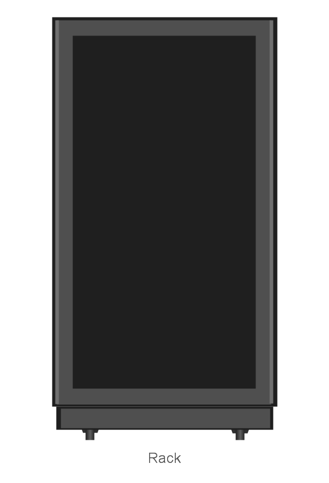
The vector stencils library "Network hardware" contains 27 clipart images and symbols of network equipment for drawing computer network diagrams.
"Networking hardware may also be known as network equipment or computer networking devices. Units which are the last receiver or generate data are called hosts or data terminal equipment.
All these terms refer to devices facilitating the use of a computer network. Specifically, they mediate data in a computer network. ...
Typically, networking hardware includes gateways, routers, network bridges, switches, hubs, and repeaters. But it also includes hybrid network devices such as multilayer switches, protocol converters, bridge routers, proxy servers, firewalls, network address translators, multiplexers, network interface controllers, wireless network interface controllers, modems, ISDN terminal adapters, line drivers, wireless access points, networking cables and other related hardware.
The most common kind of networking hardware today is a copper-based Ethernet adapter because of its standard inclusion on most modern computer systems. Wireless networking has, however, become increasingly popular, especially for portable and handheld devices.
Other hardware prevalent in computer networking includes data center equipment (such as file servers, database servers and storage areas), network services (such as DNS, DHCP, email, etc.) as well as devices which assure content delivery.
Taking a wider view, mobile phones, PDAs and even modern coffee machines may also be considered networking hardware. As technology advances and IP-based networks are integrated into building infrastructure and household utilities, network hardware will becomes an ambiguous term owing to the vastly increasing number of "network capable" endpoints." [Networking hardware. Wikipedia]
The clip art example "Network hardware -Vector stencils library" was created using the ConceptDraw PRO diagramming and vector drawing software extended with the Computer and Networks solution from the Computer and Networks area of ConceptDraw Solution Park.
www.conceptdraw.com/ solution-park/ computer-and-networks
Rack
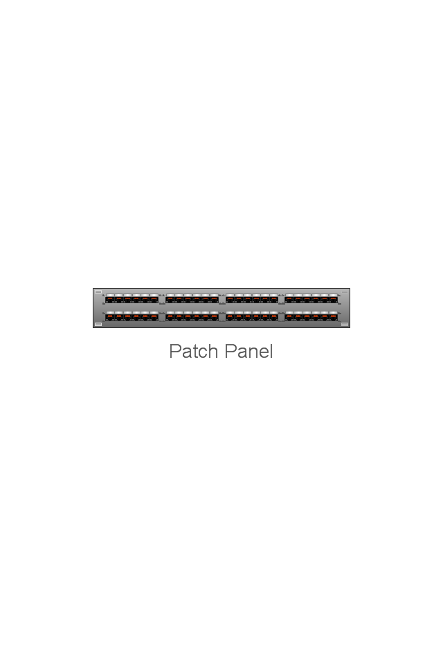
Patch Panel 48
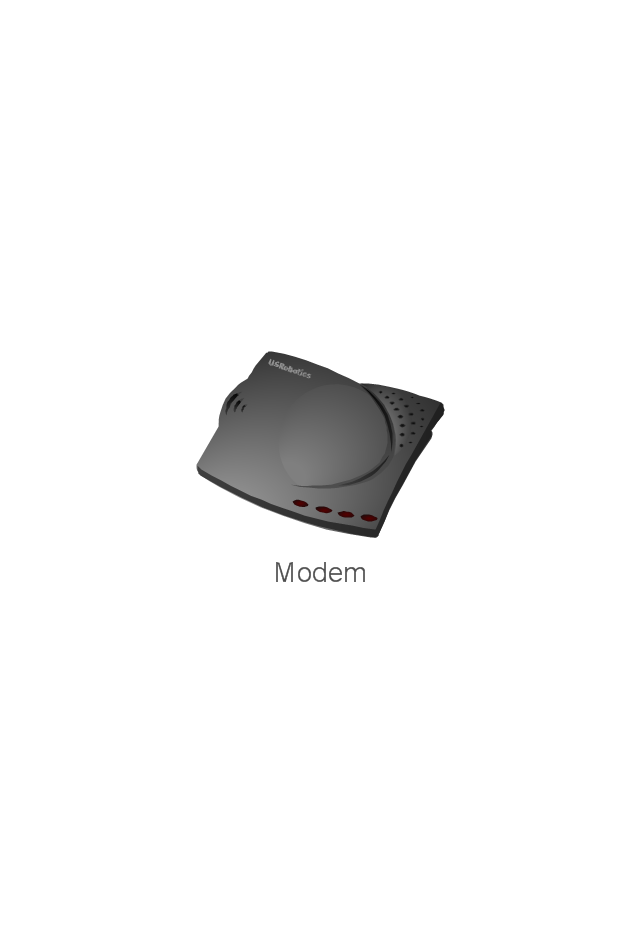
Modem
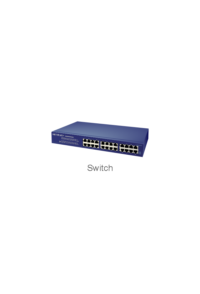
Switch
Hub

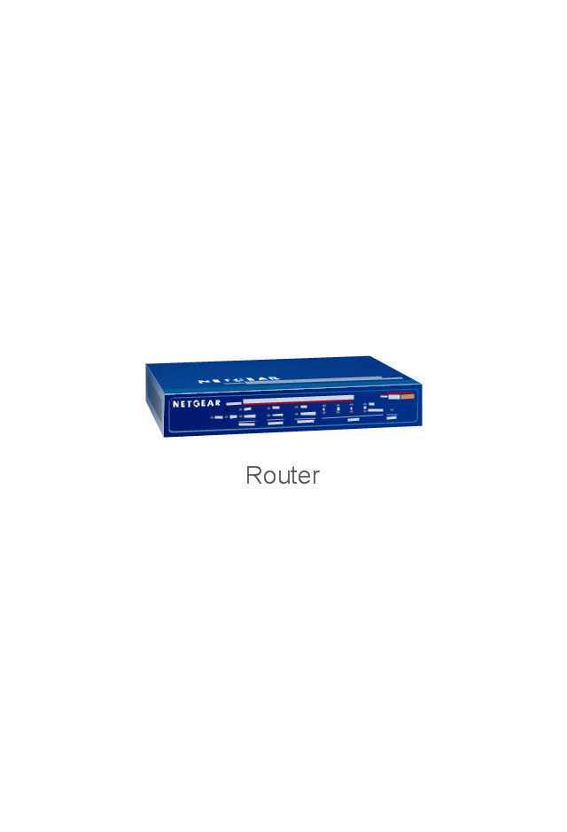
Router
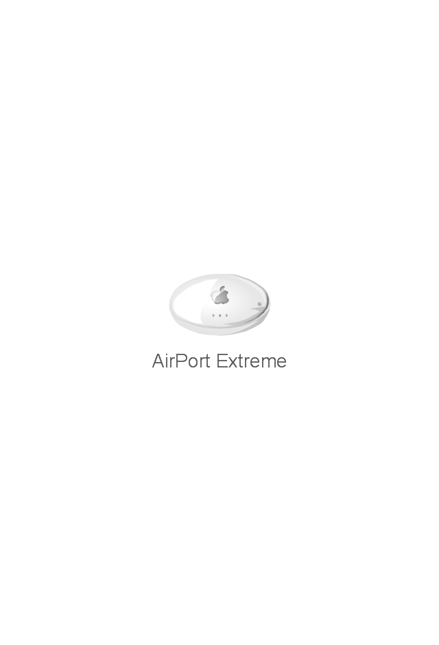
AirPort Extreme
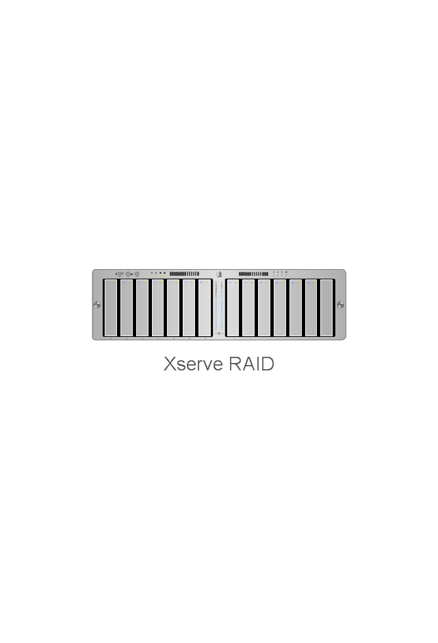
Xserve RAID
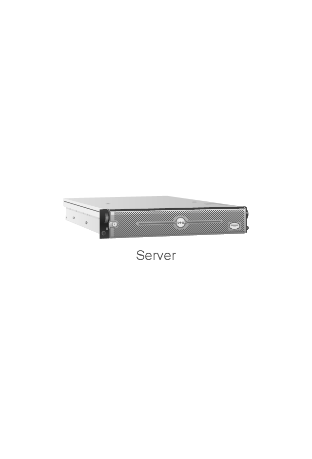
Server
Server
RAID Drive
Patch bay
UPS
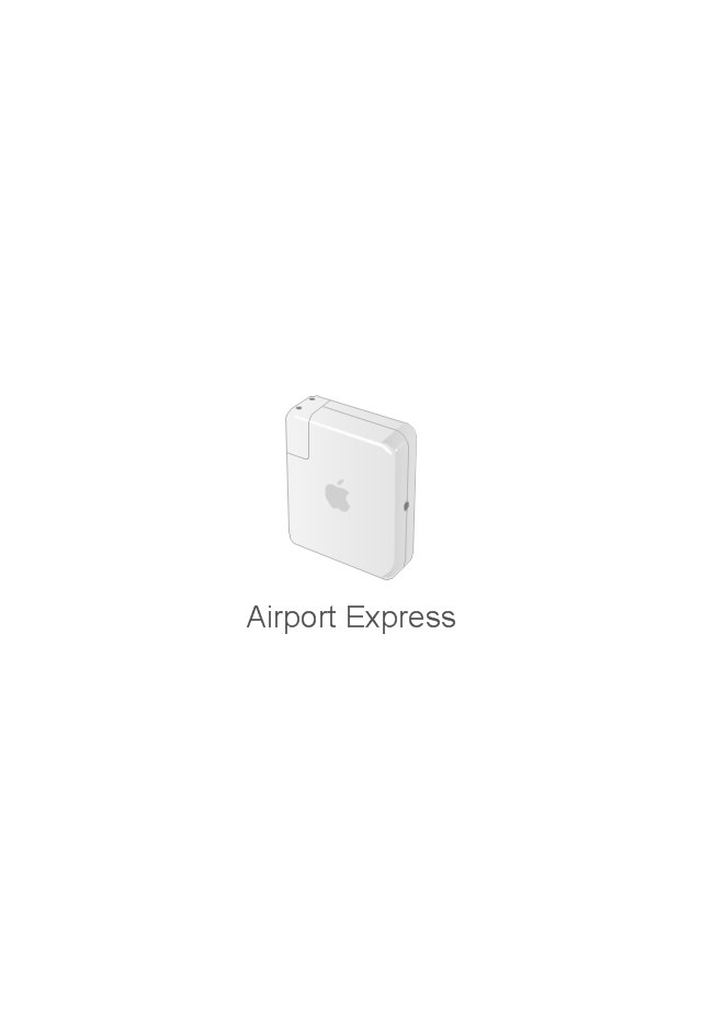
Airport Express
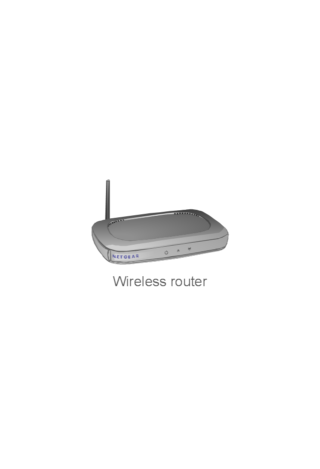
Wireless router
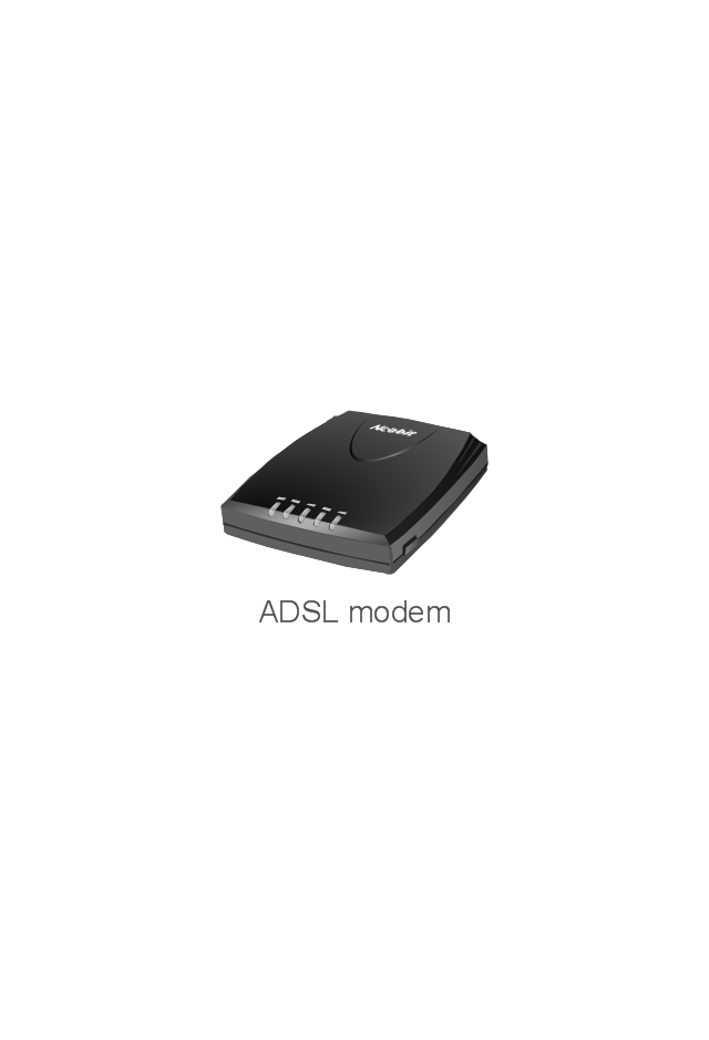
ADSL modem
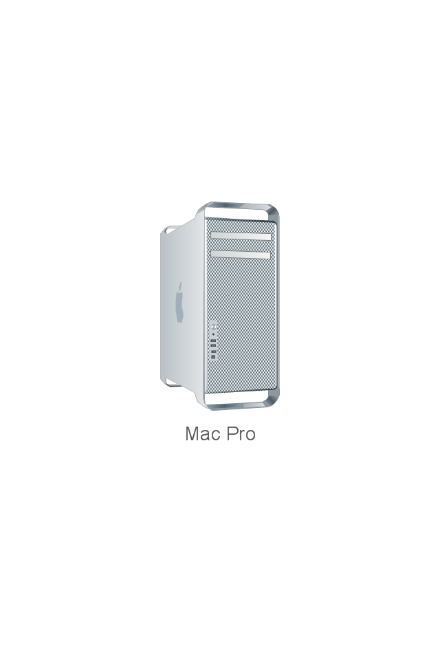
Mac Pro
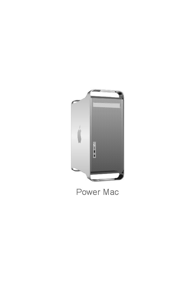
Power Mac G5
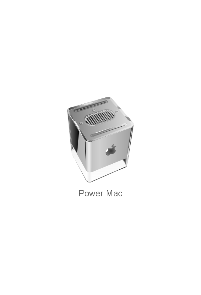
Power Mac G4 Cube
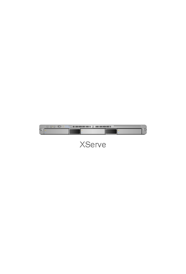
XServe
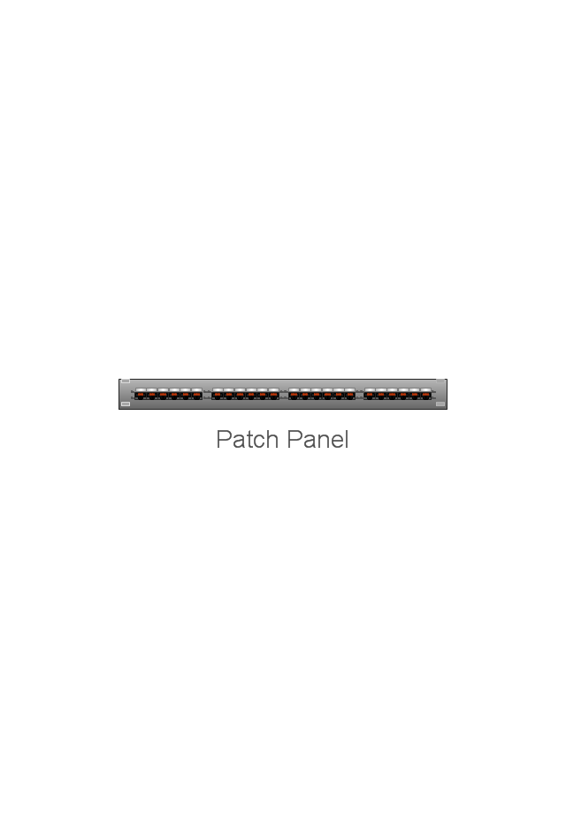
Patch Panel 24
AirPort Extreme/ Time Capsule
Switch (8 port)
-network-hardware---vector-stencils-library.png--diagram-flowchart-example.png)
Switch (16 port)
-network-hardware---vector-stencils-library.png--diagram-flowchart-example.png)
Switch (24 port)
-network-hardware---vector-stencils-library.png--diagram-flowchart-example.png)
Switch (48 port)
-network-hardware---vector-stencils-library.png--diagram-flowchart-example.png)
Patch Panel (24 port)
-network-hardware---vector-stencils-library.png--diagram-flowchart-example.png)
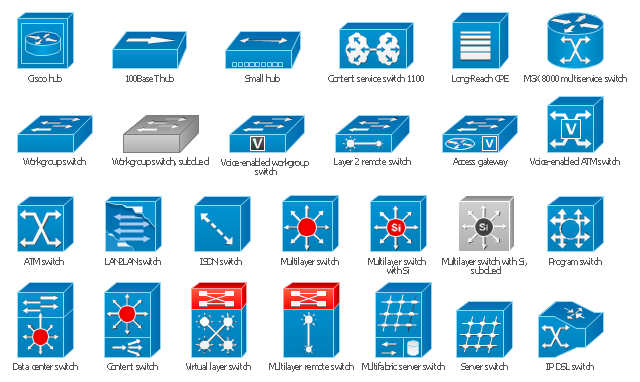
The vector stencils library "Cisco switches and hubs" contains 26 symbols for drawing computer network diagrams using the ConceptDraw PRO diagramming and vector drawing software.
"A network switch (sometimes known as a switching hub) is a computer networking device that is used to connect many devices together on a computer network. A switch is considered more advanced than a hub because a switch will only send a message to the device that needs or requests it, rather than broadcasting the same message out of each of its ports.
A switch is a multi-port network bridge that processes and forwards data at the data link layer (layer 2) of the OSI model. Some switches have additional features, including the ability to route packets. These switches are commonly known as layer-3 or multilayer switches. Switches exist for various types of networks including Fibre Channel, Asynchronous Transfer Mode, InfiniBand, Ethernet and others." [Network switch. Wikipedia]
"An Ethernet hub, active hub, network hub, repeater hub, multiport repeater or hub is a device for connecting multiple Ethernet devices together and making them act as a single network segment. It has multiple input/ output (I/ O) ports, in which a signal introduced at the input of any port appears at the output of every port except the original incoming. A hub works at the physical layer (layer 1) of the OSI model. The device is a form of multiport repeater. Repeater hubs also participate in collision detection, forwarding a jam signal to all ports if it detects a collision.
Some hubs may also come with a BNC and/ or Attachment Unit Interface (AUI) connector to allow connection to legacy 10BASE2 or 10BASE5 network segments." [Ethernet hub. Wikipedia]
The example "Design elements - Cisco switches and hubs" is included in the Cisco Network Diagrams solution from the Computer and Networks area of ConceptDraw Solution Park.
Cisco switches and hubs symbols
The vector stencils library "Cisco products additional" contains 141 symbols of computer network devices and equipment for drawing Cisco network diagrams.
The symbols example "Cisco products additional - Vector stencils library" was created using the ConceptDraw PRO diagramming and vector drawing software extended with the Cisco Network Diagrams solution from the Computer and Networks area of ConceptDraw Solution Park.
www.conceptdraw.com/ solution-park/ computer-networks-cisco
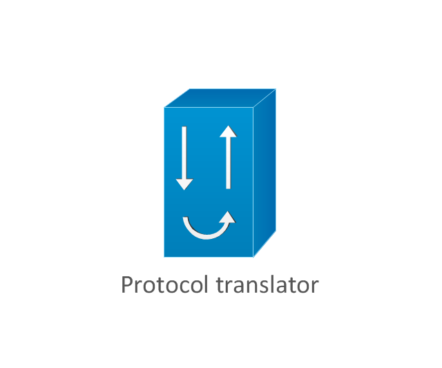
Protocol translator
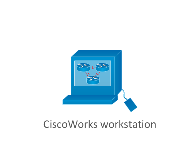
CiscoWorks workstation
Access server
Workgroup director
Network management appliance
Storage Solution Engine (SSE)
-cisco-products-additional---vector-stencils-library.png--diagram-flowchart-example.png)
Software based router on file / application server
Cisco MeetingPlace Express
PC router card
Transpath
Bridge
IOS SLB
100BaseT hub
uBR910
CDDI-FDDI
PC adapter card
VIP
CSM-S
Terminal server
Route/Switch processor with Si
Route/Switch processor
PXF
AVS (Application Velicity System)
-cisco-products-additional---vector-stencils-library.png--diagram-flowchart-example.png)
Content engine (cache director)
-cisco-products-additional---vector-stencils-library.png--diagram-flowchart-example.png)
Cisco file engine
Management engine (ME 1100)
-cisco-products-additional---vector-stencils-library.png--diagram-flowchart-example.png)
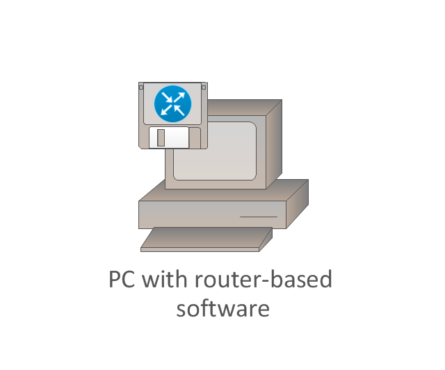
PC with router-based software
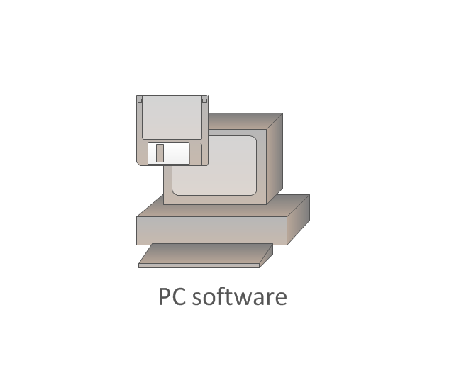
PC with software
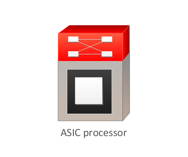
ASIC processor
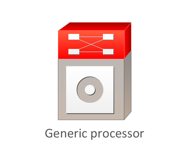
Generic processor
Switch processor
Cisco 5500 family
Multi-switch device
IP transport concentrator
ITP
Cisco CA
Voice gateway
BBSM
ATA
SIP Proxy server

MicroWeb server

NetRanger
Cisco 6920 RateMux
NetSonar
Cisco 1000
IP
System controller
ACE
Voice-enabled access server (voice-enabled communications server)
-cisco-products-additional---vector-stencils-library.png--diagram-flowchart-example.png)
Directory server
Cisco 4310 end office system
ADM
FireWall Service Module (FWSM)
-cisco-products-additional---vector-stencils-library.png--diagram-flowchart-example.png)
Cisco Unity Express
Cisco Unity Server
Centri firewall
Cisco Security Manager
Data switch processor (AKA data center switch)
-cisco-products-additional---vector-stencils-library.png--diagram-flowchart-example.png)
Cisco MP
IOS firewall
PIX firewall, right
PIX firewall, left
CallManager
Cisco 6700 Series
MGX 8240
MGX 8220
MGX 8260
DSLAM
Cisco 6732 access server
Cisco 6701
H.323
Access gateway
ICS 7750
VPN concentrator
SSL terminator
CDM (Content Distribution Manager)
-cisco-products-additional---vector-stencils-library.png--diagram-flowchart-example.png)
Cisco 15200
Cisco 15800
Content Service Module
Content Transformation Engine (CTE)
-cisco-products-additional---vector-stencils-library.png--diagram-flowchart-example.png)
Cisco VN 2900
Cisco VN 5900
Cisco VN 5902
Cisco Unified Presence Server
ICM
PC card
Access point
Dual mode access point
EtherClient
Tablet
Wireless transport
Wireless bridge
Lightweight single radio access point
Lightweight Double Radio Access Point
WLAN controller
Wi-Fi tag
Wireless location appliance
Wireless connectivity
WiSM
Mesh AP
SC2200 Signaling Controller
Virtual Switch Controller (VSC3000)
-cisco-products-additional---vector-stencils-library.png--diagram-flowchart-example.png)
VS C3000 or SC2200 host
BTS 10200 Softswitch
Detector
IP/TV content manager
IP/TV broadcast server
Universal gateway
Generic softswitch
Generic Softswitch (blue)
-cisco-products-additional---vector-stencils-library.png--diagram-flowchart-example.png)
Guard
Mobile access router
Carrier Routing System (CRS)
-cisco-products-additional---vector-stencils-library.png--diagram-flowchart-example.png)
FC storage
Intelliswitch Stack
Service control
UPC (Unified Personal Communicator)
-cisco-products-additional---vector-stencils-library.png--diagram-flowchart-example.png)
PMC
IP communicator
Streamer
Vault
DWDM filter
DWDM ring
DWDM network line
Streamer (half-full)
-cisco-products-additional---vector-stencils-library.png--diagram-flowchart-example.png)
Vault (half-full)
-cisco-products-additional---vector-stencils-library.png--diagram-flowchart-example.png)
Data center switch, reversed
Scanner
10GE/FCoE
car
CUBE
Director-class fibre channel director
Fibre channel disk subsystem
Fibre channel fabric switch
Generic gateway
Handheld
Internet streamer
JBOD
MAS gateway
Mesh AP
Mobile streamer
Electrical Symbols — Composite Assemblies

The vector stencils library "Logical symbols" contains 49 logical symbols for drawing logical network topology diagrams.
"Logical topology, or signal topology, is the arrangement of devices on a computer network and how they communicate with one another. How devices are connected to the network through the actual cables that transmit data, or the physical structure of the network, is called the physical topology. Physical topology defines how the systems are physically connected. It represents the physical layout of the devices on the network. The logical topology defines how the systems communicate across the physical topologies.
Logical topologies are bound to network protocols and describe how data is moved across the network. ... EXAMPLE : twisted pair Ethernet is a logical bus topology in a physical star topology layout. While IBM's token ring is a logical ring topology, it is physically set up in star topology." [Logical topology. Wikipedia]
The icons example "Logical symbols - Vector stencils library" was created using the ConceptDraw PRO diagramming and vector drawing software extended with the Computer and Networks solution from the Computer and Networks area of ConceptDraw Solution Park.
www.conceptdraw.com/ solution-park/ computer-and-networks
Coaxial Line Tag

Fiber Optic Line Tag

Twisted Pair Line Tag

SC2200 Signaling Controller

Bridge

Network Management Appliance

Access Server (Communications Server)
-logical-symbols---vector-stencils-library.png--diagram-flowchart-example.png)
Terminal Server

Web Browser

Security Management, Cisco

Lock and Key

Lock

Key

Relational Database

Host

CSU/DSU

WAN

University

Government building

Home Office

Telecommuter House PC

Medium Building, Regular

Headquarters, Subdued

House, Regular

Small Business

Network Connector

Dynamic Connector

Line Connector

Line-curve Connector

Bus

FDDI Ring

Peer-to-peer

Token-ring

Star

Comm-link

Curved Bus

Ethernet

Cloud

Speaker

Microphone

Router

ATM Router

ISDN Switch

ATM Switch

ATM/FastGB Etherswitch

Workgroup Switch

Small Hub

100BaseT Hub

CDDI-FDDI

Network Icon

Network diagrams with ConceptDraw DIAGRAM

Network Glossary Definition


Cisco Optical. Cisco icons, shapes, stencils and symbols

 Cisco Network Diagrams
Cisco Network Diagrams solution extends ConceptDraw DIAGRAM with the best characteristics of network diagramming software. Included samples, templates and libraries of built-in standardized vector Cisco network icons and Cisco symbols of computers, network devices, network appliances and other Cisco network equipment will help network engineers, network designers, network and system administrators, as well as other IT professionals and corporate IT departments to diagram efficiently the network infrastructure, to visualize computer networks topologies, to design Cisco computer networks, and to create professional-looking Cisco Computer network diagrams, Cisco network designs and schematics, Network maps, and Network topology diagrams in minutes.
MS Visio Look a Like Diagrams

Cisco Products Additional. Cisco icons, shapes, stencils and symbols

Cisco Network Icons

The vector stencils library "Cisco network topology" contains 89 symbols of Cisco network devices and design elements for drawing computer network topology diagrams using the ConceptDraw PRO diagramming and vector drawing software.
"Network topology is an arrangement of the various elements (links, nodes, etc.) of a computer network. Essentially, it is the topological structure of a network, and may be depicted physically or logically. Physical topology refers to the placement of the network's various components, including device location and cable installation, while logical topology shows how data flows within a network, regardless of its physical design. Distances between nodes, physical interconnections, transmission rates, and/ or signal types may differ between two networks, yet their topologies may be identical.
A good example is a local area network (LAN): Any given node in the LAN has one or more physical links to other devices in the network; graphically mapping these links results in a geometric shape that can be used to describe the physical topology of the network. Conversely, mapping the data flow between the components determines the logical topology of the network." [Network topology. Wikipedia]
The example "Design elements - Cisco network topology" is included in the Cisco Network Diagrams solution from the Computer and Networks area of ConceptDraw Solution Park.
Cisco network topology symbols

The vector stencils library "Computers and network isometric" contains 56 3D clipart images of computer and network devices and equipment for drawing network diagrams.
The clip art example "Computers and network isometric - Vector stencils library" was created using the ConceptDraw PRO diagramming and vector drawing software extended with the Computer and Networks solution from the Computer and Networks area of ConceptDraw Solution Park.
The clip art example "Computers and network isometric - Vector stencils library" was created using the ConceptDraw PRO diagramming and vector drawing software extended with the Computer and Networks solution from the Computer and Networks area of ConceptDraw Solution Park.
Laptop

DDCS

Server

Webcam

Wireless Network Storage

Personal computer

VoIP phone

Fax

Plotter

Mobile phone

Feature phone

Printer

Satellite dish

Satellite antenna

Automatic-tracking satellite dish
Wireless access point

Wireless router

Router

Network switch

Network device

Mobile GPS Terminal

GPS phone

Television antenna

Radio tower

Base station

Satellite

In-vehicle satellite telecommunication

Satellite dishes on ship

Airplane

Internet

Man

Woman

Call-center

Honeycomb

Mountain

Radio waves

Radio waves

Tower block

Office building

House

House

Globe

Wireless security camera

Truck

Tree

Conifer tree

1U hub / switch

2U hub / switch

1U server

2U Server

3U Server

4U Server

Communications satellite

Car

Radio waves

Firewall

 Computer Network Diagrams
Computer Network Diagrams solution extends ConceptDraw DIAGRAM software with samples, templates and libraries of vector icons and objects of computer network devices and network components to help you create professional-looking Computer Network Diagrams, to plan simple home networks and complex computer network configurations for large buildings, to represent their schemes in a comprehensible graphical view, to document computer networks configurations, to depict the interactions between network's components, the used protocols and topologies, to represent physical and logical network structures, to compare visually different topologies and to depict their combinations, to represent in details the network structure with help of schemes, to study and analyze the network configurations, to communicate effectively to engineers, stakeholders and end-users, to track network working and troubleshoot, if necessary.
Computer Network. Computer and Network Examples

- Symbols Of Networking Devices
- Network Icon | Local area network (LAN). Computer and Network ...
- Visio Multilayer Switch Icon
- Floor Plan With Computer Networks
- Cisco Routers. Cisco icons, shapes, stencils and symbols | Network ...
- Cisco Network Topology. Cisco icons, shapes, stencils and symbols ...
- Design elements - Network layout floorplan | Design elements ...
- Network hardware - Vector stencils library | Wireless networks ...
- Data Center Switch Symbol Png
- Network Gateway Router | Cisco Routers. Cisco icons, shapes ...
- Port Switch Symbol
- Network Hub Symbol
- Design elements - Network layout floorplan | Network Protocols ...
- Network Bridge Clipart
- Cisco switches and hubs - Vector stencils library | Network hardware ...
- Networking Symbols
- House ventilation | Floor Plans | Design elements - Network layout ...
- Logical symbols - Vector stencils library | Cisco switches and hubs ...
- Floor Plan For Computer Networking
- How To use Switches in Network Diagram | Design elements ...