 Sport Field Plans
Sport Field Plans solution extends ConceptDraw DIAGRAM with samples, templates and libraries of ready-made design elements for developing layouts of sport fields, recreation areas, playground layouts plans, and for professional drawing various sport field plans — for football, basketball, volleyball, golf, baseball, tennis, etc. Depict all your playground layout ideas easily and decisively implement the playground layout designs. Use the final colorful, strict and accurate ConceptDraw's playground layouts when designing the building documentation, brochures, booklets, advertising materials, sports editions, sport maps, business plans, on web sites of sport complexes, sport centers, hotels, etc.
Building Drawing Software for Design Sport Fields


Interior Design. Sport Fields — Design Elements

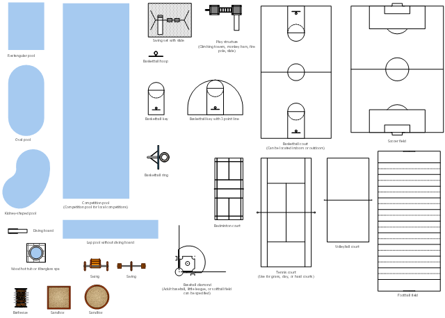
The vector stencils library "Sport fields and recreation" contains 25 shapes of sport fields and recreation design elements. Use it for drawing sport fields and recreation area plans with the ConceptDraw PRO diagramming and vector drawing software.
The vector stencils library "Sport fields and recreation" is included in the Sport Field Plans solution from the Building Plans area of ConceptDraw Solution Park.
The vector stencils library "Sport fields and recreation" is included in the Sport Field Plans solution from the Building Plans area of ConceptDraw Solution Park.
Rectangular pool
Oval pool
Kidney-shaped pool
Lap pool
Competition pool
Spa
Diving board
Swing set
Play structure
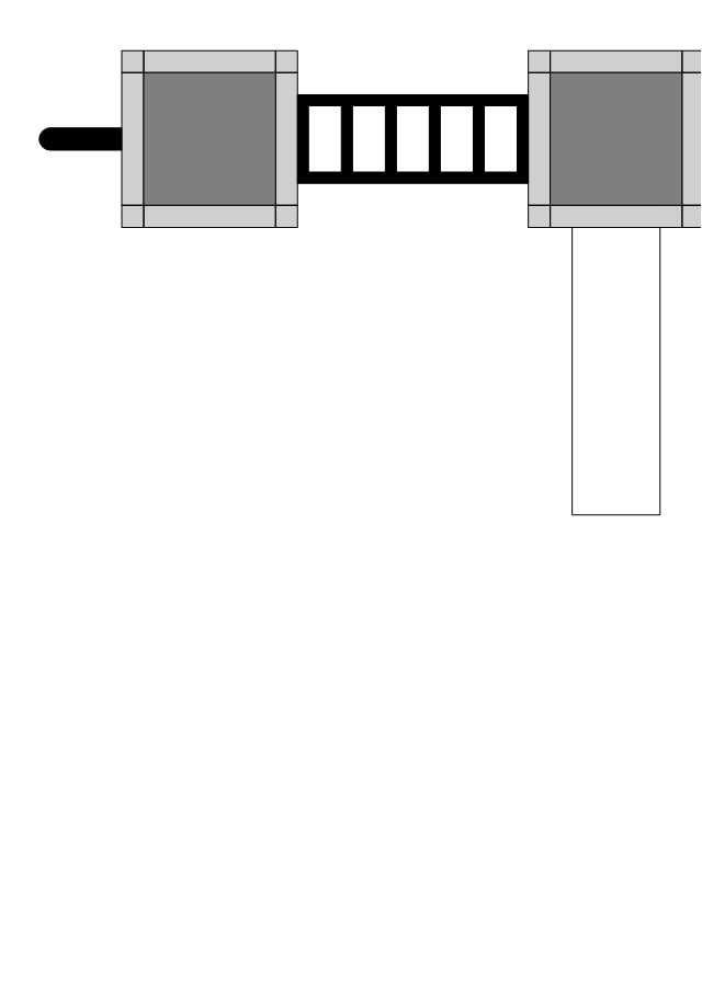
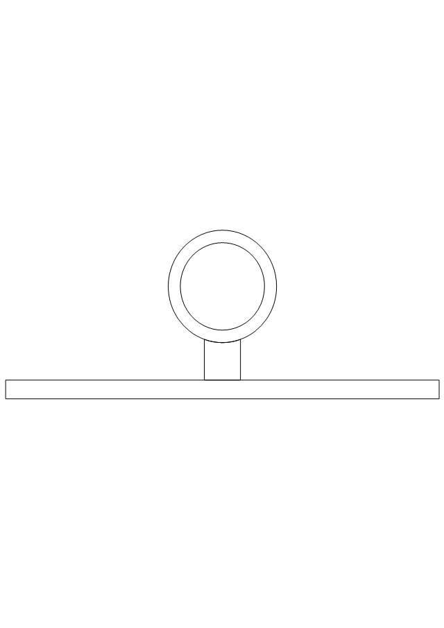
Basketball hoop
Basketball key
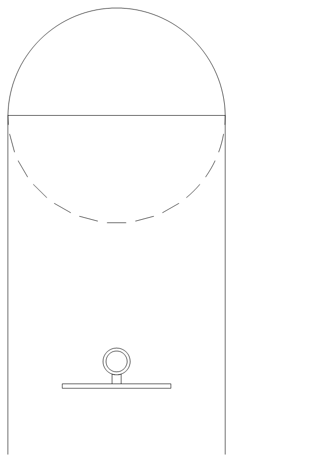
Basketball 3-pt.

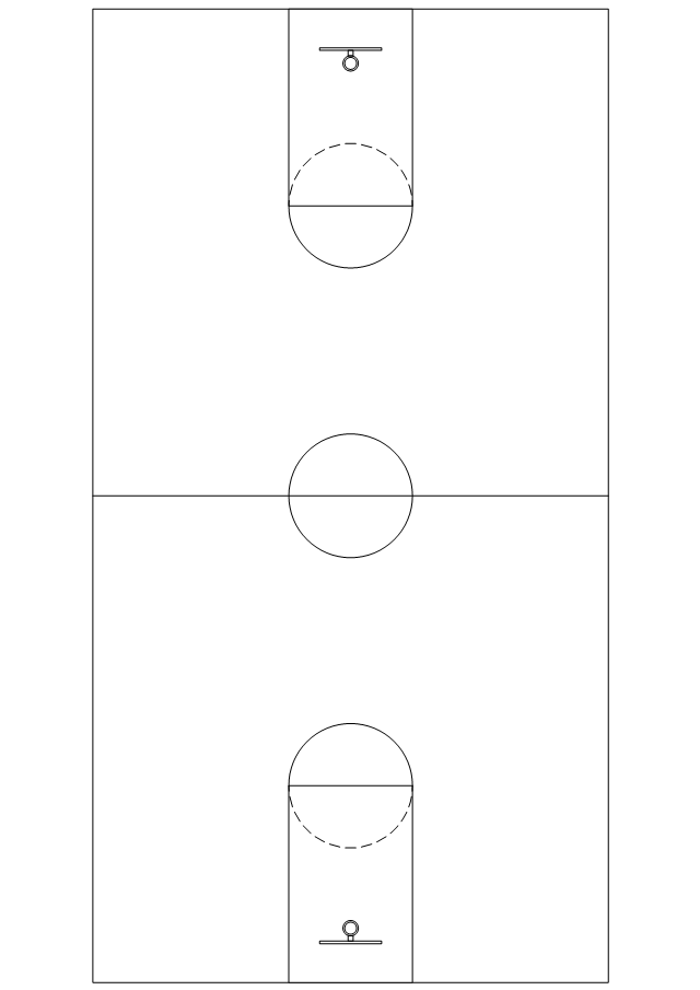
Basketball court
Badminton court
Volleyball court
Tennis court
Soccer field
Football field
Baseball diamonds
Basketball ring
Barbecue
Swing 1
Swing 2
Sand-box 1
Sand-box 2
Building Drawing Software for Design Seating Plan

Interior Design. Site Plan — Design Elements

The vector stencils library "Sport fields and recreation" contains 25 shapes of sport fields and recreation design elements. Use it for drawing sport fields and recreation area plans with the ConceptDraw PRO diagramming and vector drawing software.
The vector stencils library "Sport fields and recreation" is included in the Sport Field Plans solution from the Building Plans area of ConceptDraw Solution Park.
The vector stencils library "Sport fields and recreation" is included in the Sport Field Plans solution from the Building Plans area of ConceptDraw Solution Park.
Rectangular pool
Oval pool
Kidney-shaped pool
Lap pool
Competition pool
Spa
Diving board
Swing set
Play structure
Basketball hoop
Basketball key
Basketball 3-pt.
Basketball court
Badminton court
Volleyball court
Tennis court
Soccer field
Football field
Baseball diamonds
Basketball ring
Barbecue
Swing 1
Swing 2
Sand-box 1
Sand-box 2
The vector stencils library "Recreation signs" contains 28 pictogram symbols of recreation signs for labeling street and directional maps, locator and tourist maps, road and route maps.
"A tourist sign, often referred to as a brown sign, is a traffic sign whose purpose is to direct visitors to tourist destinations, such as historic buildings, tourist regions, caravan or camp sites, picnic areas, sporting facilities and cultural places such as museums. By international convention, brown signs with white lettering and white pictograms are often used for this purpose. ...
Basically these tourist signs have 3 main applications:
(1) Information signs and signposts that point to important tourist destinations or places of interest in the local area, for example within a village or town.
(2) Standard signs that are used to mark routes with special themes, i.e. so-called tourist or holiday routes.
(3) Tourist signs that herald the presence of nearby landscapes, towns and regions, usually on long distance routes such as motorways. They are not used as direction signs." [Tourist sign. Wikipedia]
The pictograms example "Recreation signs - Vector stencils library" was created using the ConceptDraw PRO diagramming and vector drawing software extended with the Directional Maps solution from the Maps area of ConceptDraw Solution Park.
www.conceptdraw.com/ solution-park/ maps-directional
Parking

Amphitheater

Campfire

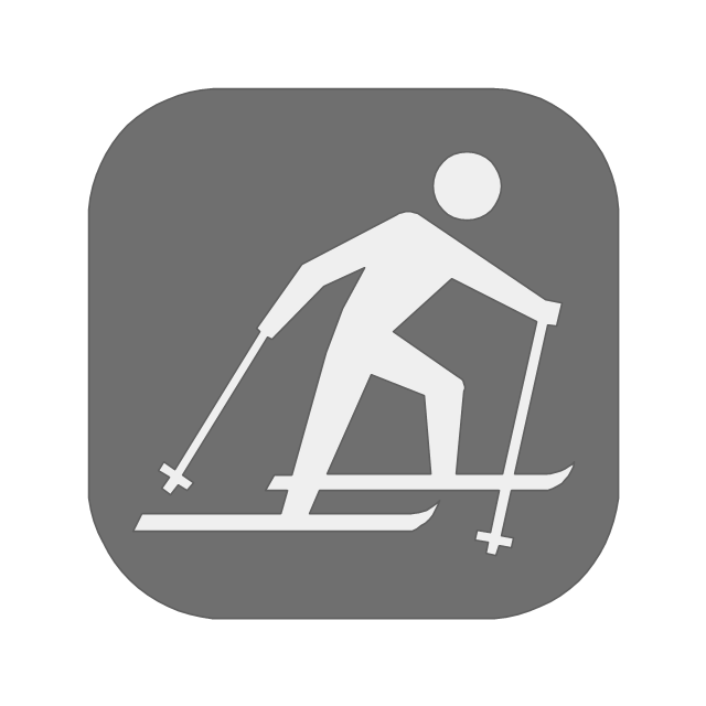
Cross-country skiing
Volleyball

Supplies/store

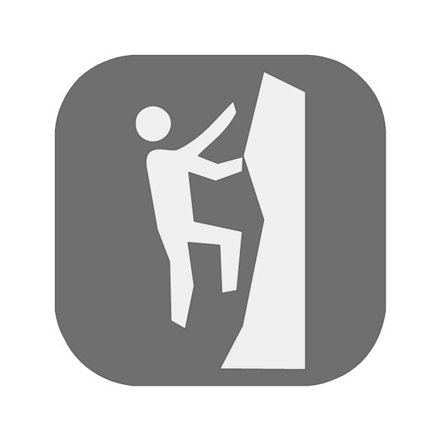
Climbing
Handball/racquetball

Boat launch

Downhill skiing

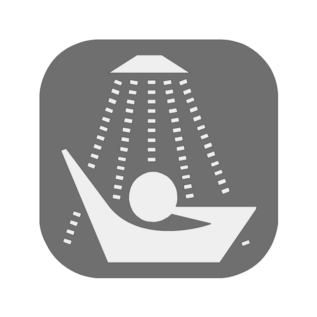
Shower
Fishing

Golf

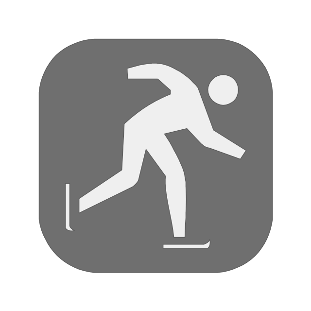
Skating
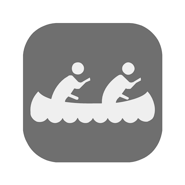
Canoe access
Horseback riding

Tennis

Kayaking

Marina

Hiking

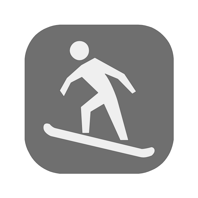
Snowboarding
Scuba diving

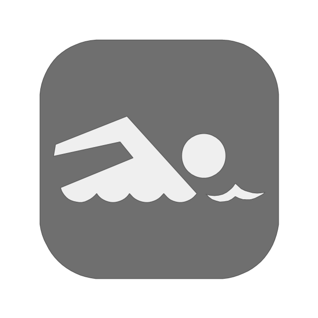
Swimming
Snowmobile

Restroom

Potable water

Campground

RV

How To Draw Building Plans

The vector stencils library "Sport fields and recreation" contains 25 shapes for drawing sport fields and recreation plans.
"A pitch is an outdoor playing area for various sports. The term is used in British and Australian English; the comparable term in American English is playing field. In most sports, the official technical term is field of play, although this is not regularly used by those outside of refereeing/ umpiring circles.
In the sport of cricket, the cricket pitch refers not to the entire field of play, but to the section of the field on which batting and bowling take place in the centre of the field. The pitch is prepared differently to the rest of the field, to provide a harder surface for bowling.
A pitch is often a regulation space, as in an association football pitch." [Pitch (sports field). Wikipedia]
The shapes example "Design elements - Sport fields and recreation" was created using the ConceptDraw PRO diagramming and vector drawing software extended with the Sport Field Plans solution from the Building Plans area of ConceptDraw Solution Park.
Sport fields and recreation design elements
The vector stencils library "Electrical and telecom" contains 83 symbols of electrical and telecommunication equipment.
Use these shapes for drawing electrical and telecom system design floor plans, cabling layout schemes, and wiring diagrams in the ConceptDraw PRO diagramming and vector drawing software.
The vector stencils library "Electrical and telecom" is included in the Electric and Telecom Plans solution from the Building Plans area of ConceptDraw Solution Park.
Luminaire ceiling mount

Enclosed ceiling luminaire

Wall light

1-light bar

2-light bar

4-light bar

6-light bar

8-light bar

Down lighter

Outdoor lightning

Outdoor lightning, bollard

Batten fluorescent, 1 lamp

Batten fluorescent, 2 lamps

Batten fluorescent, 3 lamps

Batten fluorescent, 4 lamps

Surface Fluorescent Light

Modular fluorescent fitting

Modular fluorescent fitting, inverter

Modular fluorescent fitting 2

Pull-cord switch

Emergency light

Emergency light 2

Emergency sign

Switch

Switch, 1 pole

Switch, 2 pole

Switch, 2-way

Multi-switch

Switch, intermediate

Dimmer switch

Dimmer switch 2

Socket

Socket 2

Switched socket

Switched socket 2

Double socket

Double socket 2

Socket outlet

Telephone outlet

Telephone outlet 2

Stereo outlet

Television outlet

Service panel, surface

Service panel, inset

Thermostat

Ceiling fan

Hold open unit

Detector

Fire alarm

City Fire Alarm Station

Fire Alarm Station

Fire Alarm Bell

Fire Alarm Central Station

Automatic Fire Alarm Device

Main control

Ground

Doorbell

Push Button

Buzzer

Annunciator

Horn

Maid's Signal Plug

Signal Central Station

Doorbell Chime

Doorbell Transformer

Magnetic Door Hold

Intercom

Telephone Key System

Digital Satellite System

Inside Antenna

Outside Antenna

Electric Motors

Single Phase

Three of Poly Phase

Wall Mounted Electrical Junction Box for Hardware

Wall Mounted Telephone/Data Junction Box for Hardware

Card Reader Access System

Emergency Release Button

Motion Sensor

Electric Door Opener

Watchman's Station

Watchman's Central Station

Battery

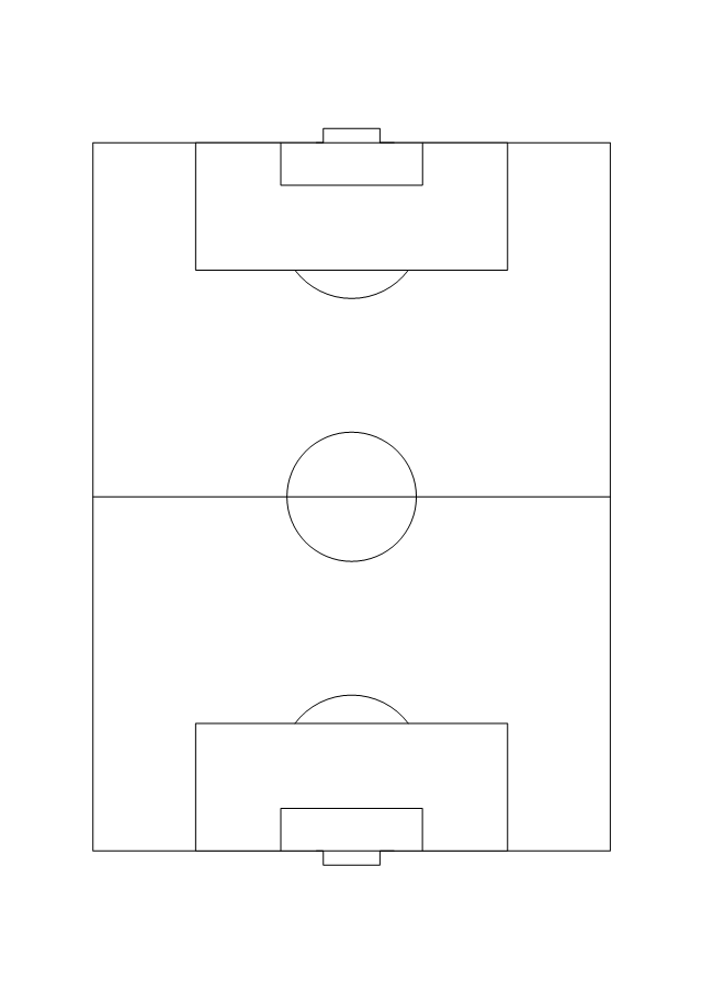
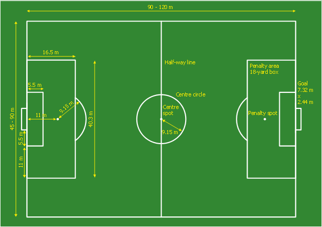
This sport field plan sample was designed on the base of the Wikipedia file: Football pitch metric.svg. [en.wikipedia.org/ wiki/ File:Football_ pitch_ metric.svg]
This file is licensed under the Creative Commons Attribution-Share Alike 3.0 Unported license. [creativecommons.org/ licenses/ by-sa/ 3.0/ deed.en]
"A football pitch (also known as a football field or soccer field) is the playing surface for the game of football made of turf. Its dimensions and markings are defined by Law 1 of the Laws of the Game, "The Field of Play".
All line markings on the pitch form part of the area which they define. For example, a ball on or above the touchline is still on the field of play; a ball on the line of the goal area is in the goal area; and a foul committed over the 16.5-metre (18-yard) line has occurred in the penalty area. Therefore a ball must completely cross the touchline to be out of play, and a ball must wholly cross the goal line (between the goal posts) before a goal is scored; if any part of the ball is still on or above the line, the ball is still in play." [Association football pitch. Wikipedia]
The sport field plan example "Football pitch metric" was created using the ConceptDraw PRO diagramming and vector drawing software extended with the Sport Field Plans solution from the Building Plans area of ConceptDraw Solution Park.
Sport field plan
Flow Chart for Olympic Sports

This pitch plan sample was designed on the base of the Wikipedia file: Comparison sport playing areas.svg.
[en.wikipedia.org/ wiki/ File:Comparison_ sport_ playing_ areas.svg]
This file is licensed under the Creative Commons Attribution-Share Alike 3.0 Unported license. [creativecommons.org/ licenses/ by-sa/ 3.0/ deed.en]
"A pitch is an outdoor playing area for various sports. The term is used in British and Australian English; the comparable term in American English is playing field. In most sports, the official technical term is field of play, although this is not regularly used by those outside of refereeing/ umpiring circles.
In the sport of cricket, the cricket pitch refers not to the entire field of play, but to the section of the field on which batting and bowling take place in the centre of the field. The pitch is prepared differently to the rest of the field, to provide a harder surface for bowling.
A pitch is often a regulation space, as in an association football pitch." [Pitch (sports field). Wikipedia]
The pitch plan example "Sport fields comparison" was created using the ConceptDraw PRO diagramming and vector drawing software extended with the Sport Field Plans solution from the Building Plans area of ConceptDraw Solution Park.
Pitch plans

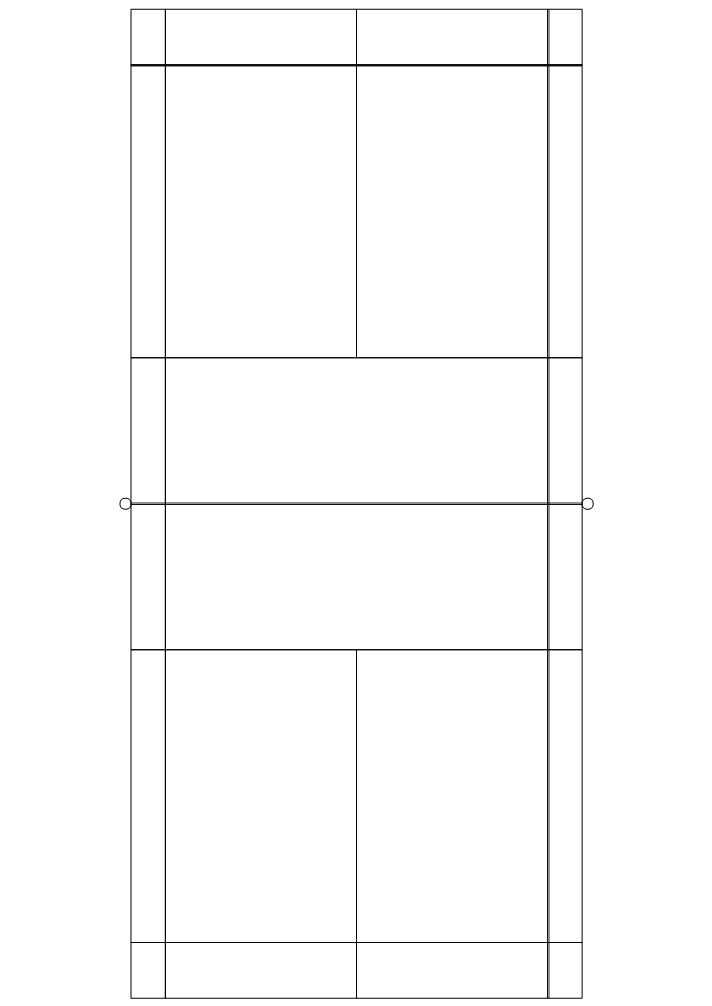
This sport field plan sample was designed on the base of the Wikipedia file: VolleyballCourt.svg. [en.wikipedia.org/ wiki/ File:VolleyballCourt.svg]
This file is licensed under the Creative Commons Attribution-Share Alike 3.0 Unported license. [creativecommons.org/ licenses/ by-sa/ 3.0/ deed.en]
"Volleyball is a team sport in which two teams of six players are separated by a net. Each team tries to score points by grounding a ball on the other team's court under organized rules. It has been a part of the official program of the Summer Olympic Games since 1964. ...
The court dimensions.
A volleyball court is 18 m (59 ft) long and 9 m (29.5 ft) wide, divided into 9 m × 9 m halves by a one-meter (40-inch) wide net. The top of the net is 2.43 m (8 ft 0 in) above the center of the court for men's competition, and 2.24 m (7 ft 4 in) for women's competition, varied for veterans and junior competitions.
The minimum height clearance for indoor volleyball courts is 7 m (23 ft), although a clearance of 8 m (26 ft) is recommended.
A line 3 m (9.84 ft) from and parallel to the net is considered the "attack line". This "3 meter" (or "10-foot") line divides the court into "back row" and "front row" areas (also back court and front court). These are in turn divided into 3 areas each: these are numbered as follows, starting from area "1", which is the position of the serving player.
After a team gains the serve (also known as siding out), its members must rotate in a clockwise direction, with the player previously in area "2" moving to area "1" and so on, with the player from area "1" moving to area "6".
The team courts are surrounded by an area called the free zone which is a minimum of 3 meters wide and which the players may enter and play within after the service of the ball. All lines denoting the boundaries of the team court and the attack zone are drawn or painted within the dimensions of the area and are therefore a part of the court or zone. If a ball comes in contact with the line, the ball is considered to be "in". An antenna is placed on each side of the net perpendicular to the sideline and is a vertical extension of the side boundary of the court. A ball passing over the net must pass completely between the antennae (or their theoretical extensions to the ceiling) without contacting them." [Volleyball. Wikipedia]
The sport field plan example "Volleyball court dimensions" was created using the ConceptDraw PRO diagramming and vector drawing software extended with the Sport Field Plans solution from the Building Plans area of ConceptDraw Solution Park.
Sport field plan

This vector stencils library contains 22 symbols of process annotations for setting automatic labels to display a datasheet field for a pipeline shape, labels, captions, outlines, off-sheet labels, text balloons, annotations, outlines, tags, and descriptions.
Use these shapes for drawing Process Flow Diagrams (PFD) and Piping and Instrumentation Diagrams (P&ID) in the ConceptDraw PRO software extended with the Chemical and Process Engineering solution from the Chemical and Process Engineering area of ConceptDraw Solution Park.
www.conceptdraw.com/ solution-park/ engineering-chemical-process
Interface point

Interface point 2 (1st half filled)
-process-annotations---vector-stencils-library.png--diagram-flowchart-example.png)
Interface point 3 (2nd half filled)
-process-annotations---vector-stencils-library.png--diagram-flowchart-example.png)
Interface point 4

Interface point 5 (1st half filled)
-process-annotations---vector-stencils-library.png--diagram-flowchart-example.png)
Interface point 6 (2nd half filled)
-process-annotations---vector-stencils-library.png--diagram-flowchart-example.png)
Slope

Off-sheet label 1

Off-sheet label 2

Off-sheet label 3

Callout 1

Callout 2

Callout 3

Callout 4

Callout 5

Callout 6

8 pt text and line

10 pt text and line

12 pt text and line

12 pt Arial text block

10 pt Arial text block

8 pt Arial text block

- Mapping Of Badminton Court
- Sport Field Plans | Badminton court | Bubble diagrams in Landscape ...
- Sport Field Plans
- Sport Field Plans | How to Create Flowchart Using Standard ...
- Network Layout Floor Plans | Sport Field Plans | Chess | Dimensions ...
- Badminton court | Sport Field Plans | Design a Soccer (Football ...
- Sport Field Plans | Volleyball court dimensions | Playground Layout ...
- Sport Field Plans | How to Create Flowchart Using Standard ...
- Sport Field Plans | Interior Design Sport Fields - Design Elements ...
- Volleyball court dimensions | Sport Field Plans | How to Create a ...
- Volleyball court dimensions | Sport Field Plans | How to Create a ...
- Sport Field Plans | Basketball Plays Software | Indoor Badminton ...
- Sport Field Plans | How To Create Restaurant Floor Plan in Minutes ...
- How to Create a Floor Plan Using ConceptDraw PRO | Planets to ...
- Sport fields and recreation - Vector stencils library | Design elements ...
- Education pictograms - Vector stencils library | Process Flowchart ...
- Volleyball court dimensions | Basketball court dimensions ...
- Badminton court | Interior Design. Sport Fields — Design Elements ...
- Sport Field Plans | Interior Design Sport Fields - Design Elements ...
- Sport Field Plans | Shuttle Court Dimensions