Swim Lane Flowchart Symbols

 Cross-Functional Flowcharts
Cross-functional flowcharts are powerful and useful tool for visualizing and analyzing complex business processes which requires involvement of multiple people, teams or even departments. They let clearly represent a sequence of the process steps, the order of operations, relationships between processes and responsible functional units (such as departments or positions).
 ConceptDraw Solution Park
ConceptDraw Solution Park collects graphic extensions, examples and learning materials
 Business Process Mapping
The Business Process Mapping solution for ConceptDraw DIAGRAM is for users involved in process mapping and creating SIPOC diagrams.
 Rapid UML
Rapid UML solution extends ConceptDraw DIAGRAM software with templates, samples and libraries of vector stencils for quick drawing the UML diagrams using Rapid Draw technology.
 Flowcharts
The Flowcharts solution for ConceptDraw DIAGRAM is a comprehensive set of examples and samples in several varied color themes for professionals that need to represent graphically a process. Solution value is added by the basic flow chart template and shapes' libraries of flowchart notation. ConceptDraw DIAGRAM flow chart creator lets one depict the processes of any complexity and length, as well as design the Flowchart either vertically or horizontally.
 Education Mind Maps
This solution extends ConceptDraw MINDMAP software with scientific and educational mind maps for educational documents, presentations, and websites.
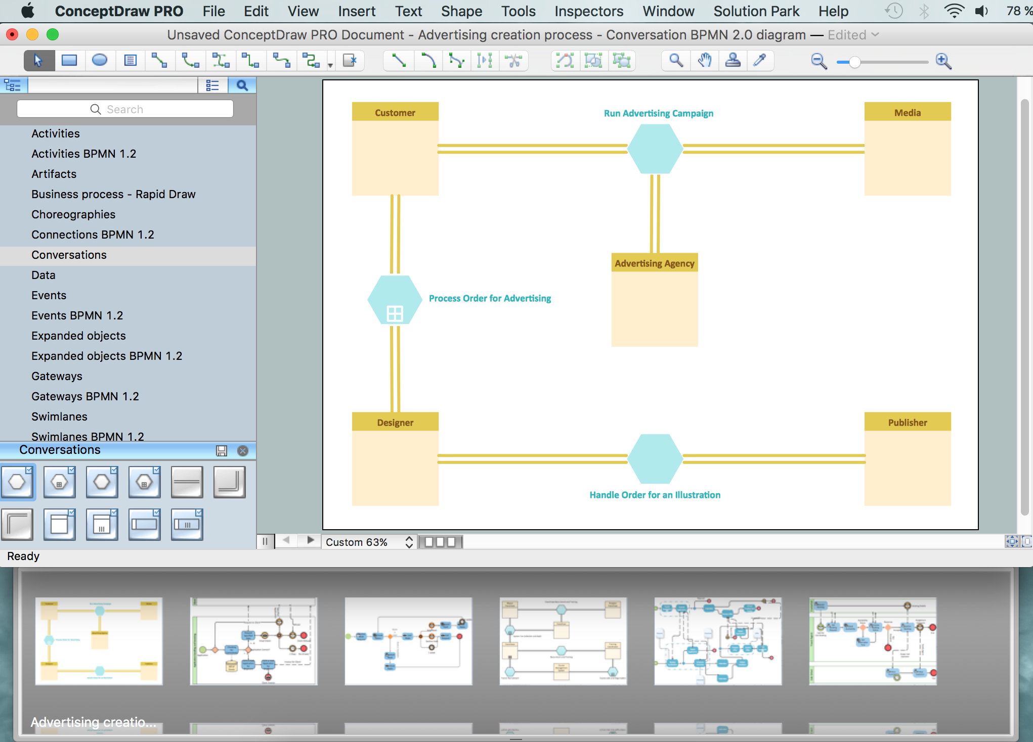
Business Process Modeling Notation
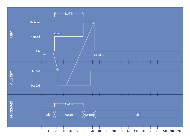
This UML timing diagram was created on the base of timing diagram example in the post "Determining Which UML Diagram to Use" from the Architexa blog.
"A project that contains many objects that frequently change state over a period of time would benefit from a Timing Diagram. Without a such a diagram you may not realize how potential periods of high traffic could intersect and overwhelm your program." [blog.architexa.com/ 2010/ 04/ determining-which-uml-diagram-to-use/ ]
This UML timing diagram example was created using the ConceptDraw PRO diagramming and vector drawing software extended with the ATM UML Diagrams solution from the Software Development area of ConceptDraw Solution Park.
UML timing diagram
Network Topologies


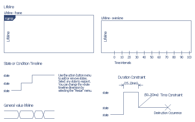
The vector stencils library "Bank UML timing diagram" contains 8 shapes for drawing UML timing diagrams.
Use it for object-oriented modeling of your bank information system.
"A timing diagram in the Unified Modeling Language 2.0 is a specific type of interaction diagram, where the focus is on timing constraints.
Timing diagrams are used to explore the behaviors of objects throughout a given period of time. A timing diagram is a special form of a sequence diagram. The differences between timing diagram and sequence diagram are the axes are reversed so that the time is increased from left to right and the lifelines are shown in separate compartments arranged vertically.
There are two basic flavors of timing diagram: the concise notation, and the robust notation." [Timing diagram. Wikipedia]
This example of UML timing diagram symbols for the ConceptDraw PRO diagramming and vector drawing software is included in the ATM UML Diagrams solution from the Software Development area of ConceptDraw Solution Park.
UML timing diagram symbols
UML Flowchart Symbols

- Rapid UML | ConceptDraw PRO | Swimlane Diagram Example For ...
- Cross-Functional Flowchart (Swim Lanes) | Swim Lane Diagrams ...
- Entity-Relationship Diagram (ERD) | Flowchart Modeling For Cash ...
- Swimlane Diagrams For Atm
- Automated payroll management system UML activity diagram | Swim ...
- Swimlane Diagram Of Employment Payroll System
- UML activity diagram - Cash withdrawal from ATM | UML Activity ...
- UML activity diagram
- Activity Diagram For Atm Banking System With Swimlanes
- Design elements - Bank UML activity diagram | Swim Lane ...
- Usecase Class Activity Swimlane Diagram For Payroll Management
- ATM UML Diagrams | UML Deployment Diagram Example - ATM ...
- UML Deployment Diagram Example - ATM System | UML Use Case ...
- Activity Diagram Of Withdrawing Cash From Atm Using Swimlane
- Use Diagram For Bank Examples
- Systems Diagram Sample
- Automated payroll management system UML activity diagram ...
- Process Flowchart | How to Create a Bank ATM Use Case Diagram ...
- Swimlane Diagram For Banking System
- Cross-Functional Flowcharts | Process Flowchart | ATM UML ...