Flowchart design. Flowchart symbols, shapes, stencils and icons


Export from ConceptDraw PRO Document to a Graphic File


"The symbols and conventions used in welding documentation are specified in national and international standards such as ISO 2553 Welded, brazed and soldered joints -- Symbolic representation on drawings and ISO 4063 Welding and allied processes -- Nomenclature of processes and reference numbers. The US standard symbols are outlined by the American National Standards Institute and the American Welding Society and are noted as "ANSI/ AWS".
In engineering drawings, each weld is conventionally identified by an arrow which points to the joint to be welded. The arrow is annotated with letters, numbers and symbols which indicate the exact specification of the weld. In complex applications, such as those involving alloys other than mild steel, more information may be called for than can comfortably be indicated using the symbols alone. Annotations are used in these cases." [Symbols and conventions used in welding documentation. Wikipedia]
The example chart "Elements of welding symbol" is redesigned using the ConceptDraw PRO diagramming and vector drawing software from the Wikipedia file: Elements of a welding symbol.PNG.
[en.wikipedia.org/ wiki/ File:Elements_ of_ a_ welding_ symbol.PNG]
The diagram example "Elements location of a welding symbol" is contained in the Mechanical Engineering solution from the Engineering area of ConceptDraw Solution Park.
Welding joint symbol chart

This cycle process chart was redesigned from the Wikimedia Commons file: Business Feedback Loop PNG version.png.
"A business ideally is continually seeking feedback from customers: are the products helpful? are their needs being met? Constructive criticism helps marketers adjust offerings to meet customer needs."
[commons.wikimedia.org/ wiki/ File:Business_ Feedback_ Loop_ PNG_ version.png]
The cycle process diagram example "Business feedback loop" was created using the ConceptDraw PRO diagramming and vector drawing software extended with the Sales Flowcharts solution from the Marketing area of ConceptDraw Solution Park.
Customers feedback cycle process chart

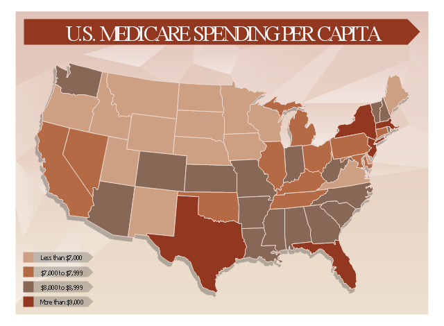
This healthcare economics infogram example was redesigned from the Wikimedia Commons file: Medicare spending per capita.png.
"Research by The Dartmouth Institute for Health Policy and Clinical Practice in the Dartmouth Atlas showed that in 2006, Medicare spending varied significantly by state. Other research quoted by the CEA Report indicated that up to 30% of Medicare costs could be saved if the middle- and high-cost states spent at the level of the lower-cost states.[1] Bear in mind that this is a Medicare comparison, so all the persons in the population analyzed are over 65.
References:
1. White House Council of Economic Advisors (CEA)-The Economic Case for Health Care Reform-June 2009-Page 19."
[commons.wikimedia.org/ wiki/ File:Medicare_ spending_ per_ capita.png]
The healthcare management thematic map sample "U.S. Medicare spending per capita" was created using the ConceptDraw PRO diagramming and vector drawing software extended with the Management Infographics solition from the area "Business Infographics" in ConceptDraw Solution Park.
Healthcare management infographics example
Process Flowchart


Circular Arrow

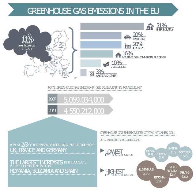
This ecology infographic example was created on the base of the infographics "Greenhouse gas emissions in the EU" from the Debating Europe website. [debatingeurope.eu/ wp-content/ uploads/ 2013/ 06/ TH_ 2_ social.png]
"A greenhouse gas (sometimes abbreviated GHG) is a gas in an atmosphere that absorbs and emits radiation within the thermal infrared range. This process is the fundamental cause of the greenhouse effect. The primary greenhouse gases in the Earth's atmosphere are water vapor, carbon dioxide, methane, nitrous oxide, and ozone. Greenhouse gases greatly affect the temperature of the Earth; without them, Earth's surface would average about 33 °C colder, which is about 59 °F below the present average of 14 °C (57 °F)." [Greenhouse gas. Wikipedia]
The ecology infographic example "EU greenhouse gas emissions" was created using the ConceptDraw PRO diagramming and vector drawing software extended with the Management Infographics solition from the area "Business Infographics" in ConceptDraw Solution Park.
Ecology infographics example
Used Solutions
This computer security diagram example was designed on the base of the Wikimedia Commons file: Firewall.png.
[commons.wikimedia.org/ wiki/ File:Firewall.png]
This file is licensed under the Creative Commons Attribution-Share Alike 3.0 Unported license. [creativecommons.org/ licenses/ by-sa/ 3.0/ deed.en]
"In computing, a firewall is a network security system that monitors and controls the incoming and outgoing network traffic based on predetermined security rules. A firewall typically establishes a barrier between a trusted, secure internal network and another outside network, such as the Internet, that is assumed to not be secure or trusted. Firewalls are often categorized as either network firewalls or host-based firewalls. Network firewalls are a software appliance running on general purpose hardware or hardware-based firewall computer appliances that filter traffic between two or more networks. Host-based firewalls provide a layer of software on one host that controls network traffic in and out of that single machine. Firewall appliances may also offer other functionality to the internal network they protect such as acting as a DHCP or VPN server for that network." [Firewall (computing). Wikipedia]
The cybersecurity diagram example "Firewall between LAN and WAN" was created using the ConceprDraw PRO software extended with the Network Security Diagrams solution from the Computer and Neworks area of ConceptDraw Solution Park.
Computer security diagram

Circular Arrows

HelpDesk
How to Create a Fault Tree Analysis Diagram (FTD) in ConceptDraw PRO

HelpDesk
How to Draw a Circular Arrows Diagram Using ConceptDraw PRO

Diagramming tool - Amazon Web Services and Cloud Computing Diagrams

- HR arrows - Vector stencils library | Cruve Arrow Icon Png
- Minimize Button Rectangle Down Arrow Png Icon
- Sales arrows - Vector stencils library | Yello Arrow Png
- Arrow Updown Png
- Combo Box Icon Png Double Arrow
- Blue Curved Arrow Png Multiple
- Sun Arrow Png
- How to Draw a Landscape Design Plan | Ribbrn Modern Arrow Png
- Movin Forward Arrow Png
- People | Arrow Long Straight Gradient Png
- Arrows Png Vector
- Circular arrows diagram - PDCA cycle | Circular Arrow | Circular ...
- Marketing Diagrams | Arrow Recycle Round Png
- Arrow Angular Png
- Basic Flowchart Symbols and Meaning | 2 Sided Curve Arrow Png
- Creative Arrow Png
- North Arrow Mark Png
- North Arrow Sketch Architect Png
- Wind Path Arrow Png
- Modern Architectural North Arrow Png