Electrical Symbols, Electrical Diagram Symbols

Electrical Drawing Software and Electrical Symbols

Circuits and Logic Diagram Software

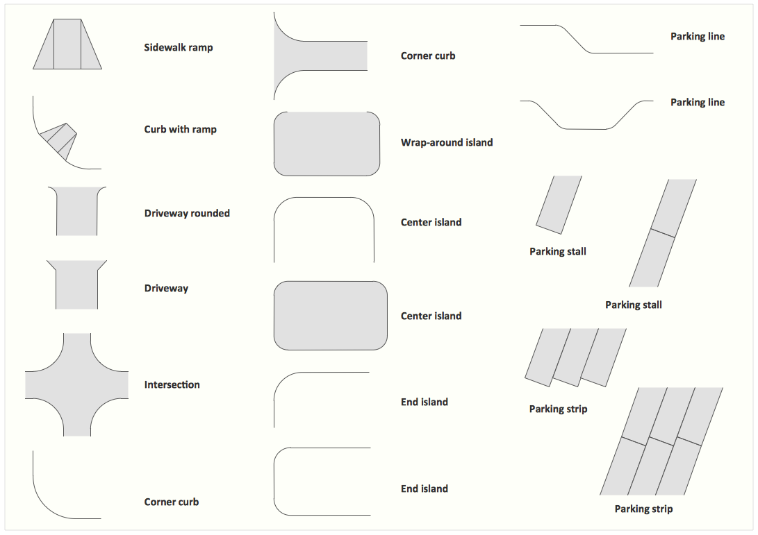
Interior Design. Site Plan — Design Elements
The vector stencils library "Fault tree analysis diagrams" contains 12 symbols for drawing Fault Tree Analysis (FTA) diagrams.
"Fault tree analysis (FTA) is a top down, deductive failure analysis in which an undesired state of a system is analyzed using Boolean logic to combine a series of lower-level events. This analysis method is mainly used in the fields of safety engineering and reliability engineering to understand how systems can fail, to identify the best ways to reduce risk or to determine (or get a feeling for) event rates of a safety accident or a particular system level (functional) failure. FTA is used in the aerospace, nuclear power, chemical and process, pharmaceutical, petrochemical and other high-hazard industries; but is also used in fields as diverse as risk factor identification relating to social service system failure.
In aerospace, the more general term "system Failure Condition" is used for the "undesired state" / Top event of the fault tree. These conditions are classified by the severity of their effects. The most severe conditions require the most extensive fault tree analysis. These "system Failure Conditions" and their classification are often previously determined in the functional Hazard analysis." [Fault tree analysis. Wikipedia]
The shapes example "Fault tree analysis diagrams" was created using the ConceptDraw PRO diagramming and vector drawing software extended with the Fault Tree Analysis Diagrams solution from the Engineering area of ConceptDraw Solution Park.
FTA diagram symbols

Building Drawing. Design Element Site Plan


Network Gateway Router


The vector stencils library "Instruments" contains 72 symbols of control instruments and measuring devices: meters and gauges, and callouts, text boxes, and inserts.
Use these shapes to create annotated process flow diagrams (PFD), flow control, manufacturing processes, and distribution system diagrams in the ConceptDraw PRO software extended with the Chemical and Process Engineering solution from the Chemical and Process Engineering area of ConceptDraw Solution Park.
www.conceptdraw.com/ solution-park/ engineering-chemical-process
Indicator local

Indicator remote

Indicator auxiliary

CRT local

CRT remote

CRT auxiliary

PLC local

PLC auxiliary

PLC remote

Computer local

Computer auxiliary

Computer remote

Light local

Light remote

Light auxiliary

Indicator auxiliary (dashed)
-instruments---vector-stencils-library.png--diagram-flowchart-example.png)
Indicator remote (dashed)
-instruments---vector-stencils-library.png--diagram-flowchart-example.png)
Steam traced auxiliary

Steam traced remote

Steam traced local

Level meter auxiliary

Level meter remote

Level meter local

Pressure gauge diaphragm

Pressure gauge

Pressure gauge liquid filled

Strain gauge

Thermometer bi-metallic

Thermometer gas

Thermometer general

Thermometer glass

Thermometer liquid

Thermometer resistance

Thermometer thermocouple

Flowmeter electromagnetic

Flowmeter general

Flowmeter nozzle

Flowmeter orifice

Flowmeter positive displacement

Flowmeter turbine

Flowmeter variable area

Flowmeter Venturi

Level meter capacitive

Level meter conductive

Level meter displacer

Level meter float

Level meter general

Level meter sonic

Indicator analoque

Indicator digital

Indicator general

Recorder analoque

Recorder digital

Recorder general

Converter

Converter 2 (1st half filled)
-instruments---vector-stencils-library.png--diagram-flowchart-example.png)
Converter 3 (2nd half filled)
-instruments---vector-stencils-library.png--diagram-flowchart-example.png)
Venturi

Venturi (pressure taps)
-instruments---vector-stencils-library.png--diagram-flowchart-example.png)
Flowmeter

Rotameter

Vortex sensor

Propeller meter

Generic utility

Operator box

Operator box 2 (1st half filled)
-instruments---vector-stencils-library.png--diagram-flowchart-example.png)
Operator box 3 (2nd half filled)
-instruments---vector-stencils-library.png--diagram-flowchart-example.png)
AND gate

OR gate

NOT gate

Correcting element

Diamond

The vector stencils library "Valves" contains 91 symbols of piping and plumbing valves.
"A valve is a device that regulates, directs or controls the flow of a fluid (gases, liquids, fluidized solids, or slurries) by opening, closing, or partially obstructing various passageways. Valves are technically valves fittings, but are usually discussed as a separate category. In an open valve, fluid flows in a direction from higher pressure to lower pressure.
The simplest, and very ancient, valve is simply a freely hinged flap which drops to obstruct fluid (gas or liquid) flow in one direction, but is pushed open by flow in the opposite direction. This is called a check valve, as it prevents or "checks" the flow in one direction.
People in developed nations use valves in their daily lives, including plumbing valves, such as taps for tap water, gas control valves on cookers, small valves fitted to washing machines and dishwashers, safety devices fitted to hot water systems..." [Valve. Wikipedia]
Use the design elements library "Valves" to draw building plans, schematic diagrams, blueprints, or technical drawings of industrial piping systems; process, vacuum, and fluids piping; hydraulics piping; air and gas piping; materials distribution; and liquid transfer systems using the ConceptDraw PRO diagramming and vector drawing software.
The shapes library "Valves" is included in the Plumbing and Piping Plans solution from the Building Plans area of ConceptDraw Solution Park.
Valve symbols

The vector stencils library Alarm and access control contains 80 symbols of digital proximity equipment, locking hardware, and access control equipment.
"An alarm device or system of alarm devices gives an audible, visual or other form of alarm signal about a problem or condition. Alarm devices are often outfitted with a siren." [Alarm device. Wikipedia]
"An access control point, which can be a door, turnstile, parking gate, elevator, or other physical barrier, where granting access can be electronically controlled. Typically, the access point is a door. An electronic access control door can contain several elements. At its most basic, there is a stand-alone electric lock. The lock is unlocked by an operator with a switch. To automate this, operator intervention is replaced by a reader. The reader could be a keypad where a code is entered, it could be a card reader, or it could be a biometric reader. Readers do not usually make an access decision, but send a card number to an access control panel that verifies the number against an access list. To monitor the door position a magnetic door switch can be used. In concept, the door switch is not unlike those on refrigerators or car doors. Generally only entry is controlled, and exit is uncontrolled. In cases where exit is also controlled, a second reader is used on the opposite side of the door. In cases where exit is not controlled, free exit, a device called a request-to-exit (REX) is used. Request-to-exit devices can be a push-button or a motion detector. When the button is pushed, or the motion detector detects motion at the door, the door alarm is temporarily ignored while the door is opened. Exiting a door without having to electrically unlock the door is called mechanical free egress. This is an important safety feature. In cases where the lock must be electrically unlocked on exit, the request-to-exit device also unlocks the door." [Access control. Wikipedia]
Use the design elements library Alarm and access control for drawing layout floor plans, blueprints, and wiring diagrams of intrusion systems, time and attendance systems, card and code access control security systems, internal and external security control systems using the ConceptDraw PRO diagramming and vector drawing software.
The shapes library Alarm and access control is included in the Security and Access Plans solution from the Building Plans area of ConceptDraw Solution Park.
Alarm and access control symbols

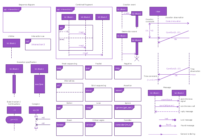
The vector stencils library "Sequence diagram" contains 32 SysML symbols.
Use it to design your sequence diagrams using ConceptDraw PRO diagramming and vector drawing software.
"A sequence diagram shows, as parallel vertical lines (lifelines), different processes or objects that live simultaneously, and, as horizontal arrows, the messages exchanged between them, in the order in which they occur. This allows the specification of simple runtime scenarios in a graphical manner. ...
If the lifeline is that of an object, it demonstrates a role. Leaving the instance name blank can represent anonymous and unnamed instances.
Messages, written with horizontal arrows with the message name written above them, display interaction. Solid arrow heads represent synchronous calls, open arrow heads represent asynchronous messages, and dashed lines represent reply messages. If a caller sends a synchronous message, it must wait until the message is done, such as invoking a subroutine. If a caller sends an asynchronous message, it can continue processing and doesn’t have to wait for a response. Asynchronous calls are present in multithreaded applications and in message-oriented middleware. Activation boxes, or method-call boxes, are opaque rectangles drawn on top of lifelines to represent that processes are being performed in response to the message (ExecutionSpecifications in UML).
Objects calling methods on themselves use messages and add new activation boxes on top of any others to indicate a further level of processing.
When an object is destroyed (removed from memory), an X is drawn on top of the lifeline, and the dashed line ceases to be drawn below it (this is not the case in the first example though). It should be the result of a message, either from the object itself, or another.
A message sent from outside the diagram can be represented by a message originating from a filled-in circle (found message in UML) or from a border of the sequence diagram (gate in UML)." [Sequence diagram. Wikipedia]
The SysML shapes example "Design elements - Sequence diagram" is included in the SysML solution from the Software Development area of ConceptDraw Solution Park.
SysML sequence diagram symbols
Mechanical Engineering

The vector stencils library "Bank UML sequence diagram" contains 34 shapes for drawing UML sequence diagrams.
Use it for object-oriented modeling of your bank information system.
"A sequence diagram shows, as parallel vertical lines (lifelines), different processes or objects that live simultaneously, and, as horizontal arrows, the messages exchanged between them, in the order in which they occur. This allows the specification of simple runtime scenarios in a graphical manner.
Diagram building blocks.
If the lifeline is that of an object, it demonstrates a role. Leaving the instance name blank can represent anonymous and unnamed instances.
Messages, written with horizontal arrows with the message name written above them, display interaction. Solid arrow heads represent synchronous calls, open arrow heads represent asynchronous messages, and dashed lines represent reply messages. ...
Activation boxes, or method-call boxes, are opaque rectangles drawn on top of lifelines to represent that processes are being performed in response to the message (ExecutionSpecifications in UML).
Objects calling methods on themselves use messages and add new activation boxes on top of any others to indicate a further level of processing.
When an object is destroyed (removed from memory), an X is drawn on top of the lifeline, and the dashed line ceases to be drawn below it ...
A message sent from outside the diagram can be represented by a message originating from a filled-in circle (found message in UML) or from a border of the sequence diagram (gate in UML)." [Sequence diagram. Wikipedia]
This example of UML sequence diagram symbols for the ConceptDraw PRO diagramming and vector drawing software is included in the ATM UML Diagrams solution from the Software Development area of ConceptDraw Solution Park.
UML sequence diagram symbols

The vector stencils library "Transistors" contains 30 symbols of transistors drawing electronic schematics and circuit diagrams.
"A transistor is a semiconductor device used to amplify and switch electronic signals and electrical power. It is composed of semiconductor material with at least three terminals for connection to an external circuit. A voltage or current applied to one pair of the transistor's terminals changes the current through another pair of terminals. Because the controlled (output) power can be higher than the controlling (input) power, a transistor can amplify a signal. Today, some transistors are packaged individually, but many more are found embedded in integrated circuits.
The transistor is the fundamental building block of modern electronic devices, and is ubiquitous in modern electronic systems. ...
Transistors are categorized by:
(1) Semiconductor material...: the metalloids germanium ... and silicon ... in amorphous, polycrystalline and monocrystalline form; the compounds gallium arsenide ... and silicon carbide ..., the alloy silicon-germanium ..., the allotrope of carbon graphene ...
(2) Structure: BJT, JFET, IGFET (MOSFET), insulated-gate bipolar transistor, "other types"
(3) Electrical polarity (positive and negative): n–p–n, p–n–p (BJTs); n-channel, p-channel (FETs)
(4) Maximum power rating: low, medium, high
(5) Maximum operating frequency: low, medium, high, radio (RF), microwave frequency...
(6) Application: switch, general purpose, audio, high voltage, super-beta, matched pair
(7) Physical packaging: through-hole metal, through-hole plastic, surface mount, ball grid array, power modules...
(8) Amplification factor..." [Transistor. Wikipedia]
The shapes example "Design elements - Transistors" was drawn using the ConceptDraw PRO diagramming and vector drawing software extended with the Electrical Engineering solution from the Engineering area of ConceptDraw Solution Park.
Transistor symbols

- Basic Flowchart Symbols and Meaning | Flowchart design ...
- Logic gate diagram - Vector stencils library | Design elements ...
- Design elements - Logic gate diagram | Electrical Symbols ...
- Logic gate diagram - Vector stencils library | Symbol Of Nand Gate ...
- Symbol Of And Gate In Technical Drawing
- Basic Flowchart Symbols and Meaning | Flowchart design ...
- Design elements - Logic gate diagram | Electrical Drawing Software ...
- Design elements - Logic gate diagram | Electrical Drawing Software ...
- Various Gates Symbol
- Drawing Of Logic Gate Symbol
- Logic gate diagram - Template | Engineering | Electrical Drawing ...
- Circuits and Logic Diagram Software | Electrical Drawing Software ...
- Process Flow Diagram Symbols | Process Flowchart | Process Flow ...
- Electrical Diagram Symbols | Electrical Schematic Symbols | Design ...
- Symbols Of Logic Gate
- Elements location of a welding symbol | Cisco Network Design ...
- Entity Relationship Diagram Symbols and Meaning ERD Symbols ...
- Basic Flowchart Symbols and Meaning | Process Flowchart ...
- Electrical Symbols , Electrical Diagram Symbols | Wiring Diagrams ...
- Fault Symbol