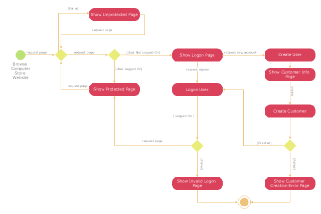
"A registered user is one who uses a program or a website and provides his/ her credentials, effectively proving his/ her identity. ...
Generally speaking, any person can become a registered user by providing some credentials, usually in the form of a username (or email) and password. After that, one can access information and privileges unavailable to non-registered users, usually referred to simply as guests. The action of providing the proper credentials for a website is called logging in, or signing in." [Registered user. Wikipedia]
The UML activity diagram example "User registration" was created using the ConceptDraw PRO diagramming and vector drawing software extended with the Rapid UML solution from the Software Development area of ConceptDraw Solution Park.
UML activity diagram
Diagramming Software for Design UML Activity Diagrams


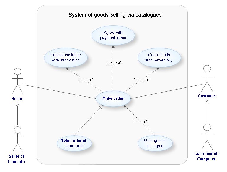
UML Use Case Diagram Example. Registration System

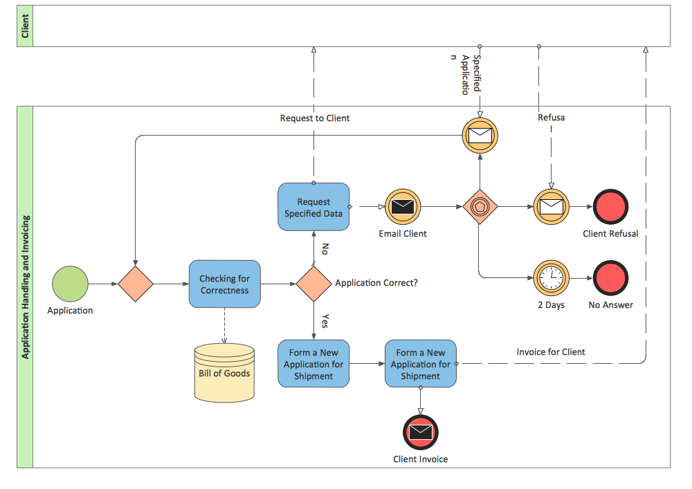
This example of automated payroll management system UML activity diagram was created on the base of figure on the webpage "Automated payroll management system" from ethelmandane.wikispaces.com.
"In the Philippines and in other foreign countries the government has a trend to embrace automation for process efficiency. One of the processes that are being automated is the payroll process. Payroll is the total amount required to pay workers and employees during a week, month or other period.
One of the government offices that desires to automate their payroll system is the NSO Camarines Sur which is located 2nd Floor MMCN Building, Panganiban Avenue, Naga City. The National Statistics Office (NSO) envisions to be recognized as a world-class provider of statistical and civil registration products and services and lives with its mission to produces and provides quality statistical and civil registration products and services. ...
The project seeks to create an Information System Plan for an Automated Payroll Management System. ...
The creation of the Information System Plan will benefit the accounting section of the organization. Specifically it is significant to:
1. Administrative Assistants. It will help to lessen time and effort in preparing and computing the salary of the employee.
2. NSO. It will help the organization to be more productive and efficient."
[ethelmandane.wikispaces.com/ ]
This file is licensed under a Creative Commons Attribution Share-Alike 3.0 License. [creativecommons.org/ licenses/ by-sa/ 3.0/ ]
This UML activity diagram example modeling the automated payroll management system using automated teller machine (ATM) was created using the ConceptDraw PRO diagramming and vector drawing software extended with the ATM UML Diagrams solution from the Software Development area of ConceptDraw Solution Park.
UML activity diagram of automated payroll management system using ATM

 Rapid UML
Rapid UML solution extends ConceptDraw DIAGRAM software with templates, samples and libraries of vector stencils for quick drawing the UML diagrams using Rapid Draw technology.
 Event-driven Process Chain Diagrams
Event-Driven Process Chain Diagrams solution extends ConceptDraw DIAGRAM functionality with event driven process chain templates, samples of EPC engineering and modeling the business processes, and a vector shape library for drawing the EPC diagrams and EPC flowcharts of any complexity. It is one of EPC IT solutions that assist the marketing experts, business specialists, engineers, educators and researchers in resources planning and improving the business processes using the EPC flowchart or EPC diagram. Use the EPC solutions tools to construct the chain of events and functions, to illustrate the structure of a business process control flow, to describe people and tasks for execution the business processes, to identify the inefficient businesses processes and measures required to make them efficient.
UML Use Case Diagram Example. Services UML Diagram. ATM system

UML Deployment Diagram Example - ATM System UML diagrams

UML Activity Diagram

UML Package Diagram. Design Elements

ConceptDraw DIAGRAM UML Diagrams with ConceptDraw DIAGRAM
UML Business Process

UML Diagram

BPMN 2.0
- Activity Diagram For User Registration
- UML Use Case Diagram Example Registration System ...
- UML Activity Diagram | Diagramming Software for Design UML ...
- Activity Diagram For Member Registration In Library System
- Activity Diagram Vehicle Registration System
- UML activity diagram - User registration | UML Use Case Diagram ...
- UML activity diagram - User registration
- Step Of Activity Diagram For User Registration In Pdf
- UML Activity Diagram | UML activity diagram - User registration ...
- Automated payroll management system UML activity diagram | Civil ...
- UML Use Case Diagram Example Registration System | UML activity ...
- UML activity diagram - User registration | How to Install and Activate ...
- UML activity diagram - User registration | UML Deployment Diagram ...
- UML activity diagram - User registration | Event-driven Process ...
- UML activity diagram - User registration | UML Activity Diagram ...
- Swimlane Activity Diagram For Registration
- UML activity diagram - User registration | UML activity diagram ...
- UML Activity Diagram | Diagramming Software for Design UML ...
- Swimlanes Activity Diagram In Log In