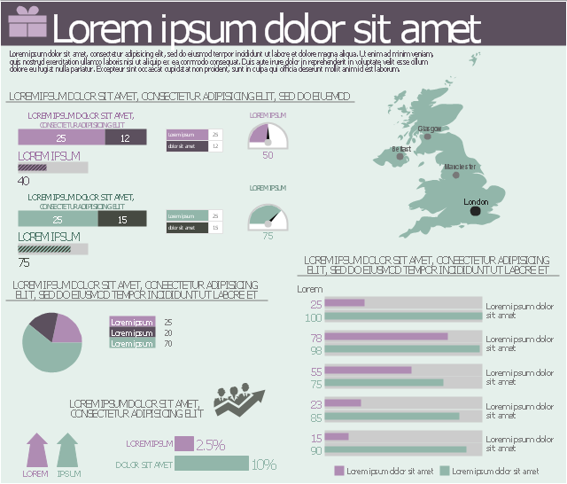
This marketing infographic template consists of design elements: title block, callout blocks, pictograms, thematic map, divided bar diagrams, pie chart, bullet indicators, arrow chart indicator, horizontal bar graph indicator, semi-radial gauge indicators.
Use it to create your marketing infograms in the ConceptDraw PRO diagramming and vector drawing software.
The template "Marketing infogram 4" is included in the Marketing Infographics solution from the Business Infographics area of ConceptDraw Solution Park.
Use it to create your marketing infograms in the ConceptDraw PRO diagramming and vector drawing software.
The template "Marketing infogram 4" is included in the Marketing Infographics solution from the Business Infographics area of ConceptDraw Solution Park.
Marketing infogram template
Used Solutions
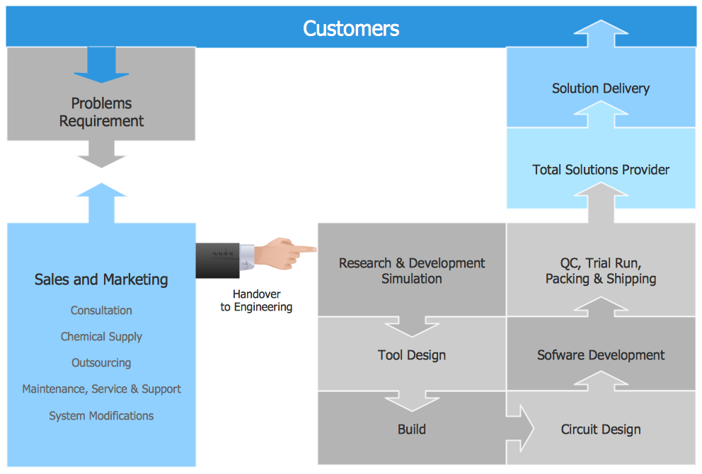
Functional Flow Block Diagram
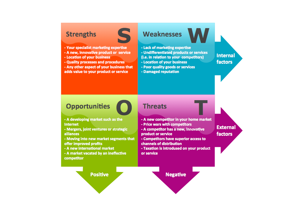
Swot Analysis Examples
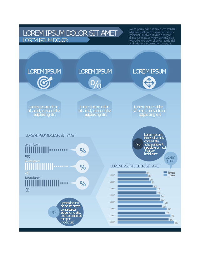
This template contains common design elements of business infographic: title and text blocks, callouts, charts and pictograms.
Use this template to create your own management infogram using the ConceptDraw PRO diagramming and vector drawing software and the Management Infographics solition from the area "Business Infographics" in ConceptDraw Solution Park.
Use this template to create your own management infogram using the ConceptDraw PRO diagramming and vector drawing software and the Management Infographics solition from the area "Business Infographics" in ConceptDraw Solution Park.
Management infogram template
Used Solutions
"Directional control valves route the fluid to the desired actuator. They usually consist of a spool inside a cast iron or steel housing. The spool slides to different positions in the housing, and intersecting grooves and channels route the fluid based on the spool's position.
The spool has a central (neutral) position maintained with springs; in this position the supply fluid is blocked, or returned to tank. Sliding the spool to one side routes the hydraulic fluid to an actuator and provides a return path from the actuator to tank. When the spool is moved to the opposite direction the supply and return paths are switched. When the spool is allowed to return to neutral (center) position the actuator fluid paths are blocked, locking it in position.
Directional control valves are usually designed to be stackable, with one valve for each hydraulic cylinder, and one fluid input supplying all the valves in the stack.
Tolerances are very tight in order to handle the high pressure and avoid leaking, spools typically have a clearance with the housing of less than a thousandth of an inch (25 µm). The valve block will be mounted to the machine's frame with a three point pattern to avoid distorting the valve block and jamming the valve's sensitive components.
The spool position may be actuated by mechanical levers, hydraulic pilot pressure, or solenoids which push the spool left or right. A seal allows part of the spool to protrude outside the housing, where it is accessible to the actuator.
The main valve block is usually a stack of off the shelf directional control valves chosen by flow capacity and performance. Some valves are designed to be proportional (flow rate proportional to valve position), while others may be simply on-off. The control valve is one of the most expensive and sensitive parts of a hydraulic circuit." [Hydraulic machinery. Wikipedia]
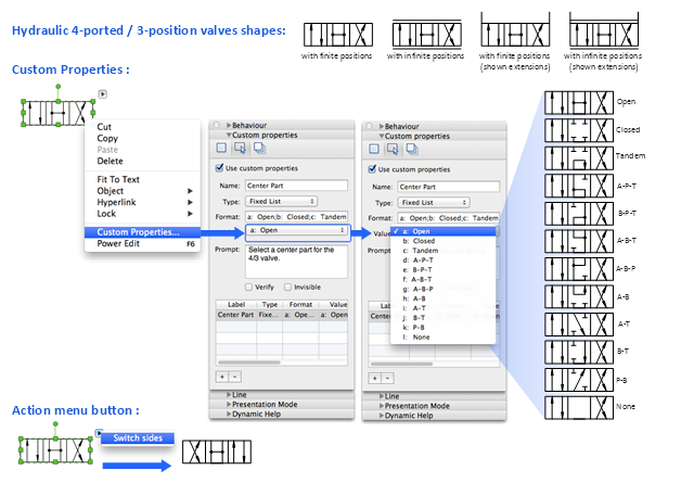
The Mac template "Hydraulic 4-ported 3-position valve" for the ConceptDraw PRO diagramming and vector drawing software is included in the Mechanical Engineering solution from the Engineering area of ConceptDraw Solution Park.
www.conceptdraw.com/ solution-park/ engineering-mechanical
The spool has a central (neutral) position maintained with springs; in this position the supply fluid is blocked, or returned to tank. Sliding the spool to one side routes the hydraulic fluid to an actuator and provides a return path from the actuator to tank. When the spool is moved to the opposite direction the supply and return paths are switched. When the spool is allowed to return to neutral (center) position the actuator fluid paths are blocked, locking it in position.
Directional control valves are usually designed to be stackable, with one valve for each hydraulic cylinder, and one fluid input supplying all the valves in the stack.
Tolerances are very tight in order to handle the high pressure and avoid leaking, spools typically have a clearance with the housing of less than a thousandth of an inch (25 µm). The valve block will be mounted to the machine's frame with a three point pattern to avoid distorting the valve block and jamming the valve's sensitive components.
The spool position may be actuated by mechanical levers, hydraulic pilot pressure, or solenoids which push the spool left or right. A seal allows part of the spool to protrude outside the housing, where it is accessible to the actuator.
The main valve block is usually a stack of off the shelf directional control valves chosen by flow capacity and performance. Some valves are designed to be proportional (flow rate proportional to valve position), while others may be simply on-off. The control valve is one of the most expensive and sensitive parts of a hydraulic circuit." [Hydraulic machinery. Wikipedia]
The Mac template "Hydraulic 4-ported 3-position valve" for the ConceptDraw PRO diagramming and vector drawing software is included in the Mechanical Engineering solution from the Engineering area of ConceptDraw Solution Park.
www.conceptdraw.com/ solution-park/ engineering-mechanical
Hydraulic directional control valve
Local area network (LAN). Computer and Network Examples
 diagram")

Process Flowchart


Context Diagram Template

This template shows the Context Diagram. It was created in ConceptDraw DIAGRAM diagramming and vector drawing software using the Block Diagrams Solution from the “Diagrams” area of ConceptDraw Solution Park. The context diagram graphically identifies the system. external factors, and relations between them. It’s a high level view of the system. The context diagrams are widely used in software engineering and systems engineering for designing the systems that process the information.
Block Diagram

- Sample 4 Blocker Swot Analysis
- 4 Blocker Template For Project Management
- 4 Blocker Example
- Block diagram - Gap model of service quality | Service 4 Ss fishbone ...
- 3D Block diagram - Template | Basic Diagramming | Block Diagrams ...
- Network Drawing Software | 4 -level 3D pyramid diagram - Template ...
- Hydraulic 4 -ported 3-position valve template - Win | Mechanical ...
- Circular Flow Diagram Template | Circular Arrows | Circular Arrow ...
- Process Flowchart | Context Diagram Template | Block Diagram ...
- Block Diagrams | Create Block Diagram | Block Diagram Of Project ...