The vector stencils library "Cable TV" contains 64 symbols of cable TV network equipment.
Use these shapes for drawing CATV system design floor plans, network topology diagrams, wiring diagrams and cabling layout schemes in the ConceptDraw PRO diagramming and vector drawing software.
The vector stencils library "Cable TV" is included in the Electric and Telecom Plans solution from the Building Plans area of ConceptDraw Solution Park.
Output Directional Tap 1

Output Directional Tap 2

Output Directional Tap 3

Output Directional Tap 4

Output Directional Tap 5

2-way Splitter

3-way Splitter

4-way Splitter

AC Power Block

Bond

Down Guy

Building Guy and Anchor

Rock Guy with Anchor

Down Guy with Anchor

Pole-to-Pole Guy

Sidewalk Down Guy with Anchor

Sidewalk Down Guy

Slack Span Messenger Wire

Tensioned Messenger Wire w/out cable

Tensioned Messenger Wire

Ground

Joint Usage (Power & Telephone Pole)
-cable-tv---vector-stencils-library.png--diagram-flowchart-example.png)
Joint Usgae Pole with Transformer

Strut

Tree Guy with Anchor

Push Brace (smaller pole in actual relative position)
-cable-tv---vector-stencils-library.png--diagram-flowchart-example.png)
Extension Arm

Built CATV Pole

Proposed CATV Pole

Directional Tap 1

Directional Tap 2

Manhole

Telephone Pole

Riser Pole

Vault Handheld

Fixed Equalizer

Fixed Flat Attenuators

Other Supporting Structures

Pedestal - Underground Routing

Power Pole

Direct Buried Underground Routing

Duct Line Underground Routing

Line Terminations

2-Way Optical Splice Location

3-Way Optical Splice Location

4-Way Optical Splice Location

> 4-Way Optical Splice Location

Optical Amplifier

Cable AC Power Combiner

Optical Fiber Cable

Optical Connector

Wavelength Demultiplexer

Wavelength Multiplexer

Optical Transmitter

Optical Transmitter

Optical Node

Optical Splitter

Headend (Signal Processing)
-cable-tv---vector-stencils-library.png--diagram-flowchart-example.png)
Node

Primary Hub

Secondary Hub

Coaxial Splice

Power Supply

Variable Equalizer

Network wiring cable. Computer and Network Examples

This example was created in ConceptDraw DIAGRAM using the Computer and Networks solution from the Computer and Networks area of ConceptDraw Solution Park.

"In computer networks, networked computing devices pass data to each other along data connections. The connections (network links) between nodes are established using either cable media or wireless media. ...
Network computer devices that originate, route and terminate the data are called network nodes. Nodes can include hosts such as personal computers, phones, servers as well as networking hardware. ...
Network links.
The communication media used to link devices to form a computer network include electrical cable (HomePNA, power line communication, G.hn), optical fiber (fiber-optic communication), and radio waves (wireless networking). In the OSI model, these are defined at layers 1 and 2 - the physical layer and the data link layer.
A widely adopted family of communication media used in local area network (LAN) technology is collectively known as Ethernet. The media and protocol standards that enable communication between networked devices over Ethernet are defined by IEEE 802.3. Ethernet transmit data over both copper and fiber cables. Wireless LAN standards (e.g. those defined by IEEE 802.11) use radio waves, or others use infrared signals as a transmission medium. Power line communication uses a building's power cabling to transmit data. ...
Network nodes.
Apart from the physical communications media described above, networks comprise additional basic system building blocks, such as network interface controller (NICs), repeaters, hubs, bridges, switches, routers, modems, and firewalls." [Computer network. Wikipedia]
The network equipment and cabling layout floorplan template for the ConceptDraw PRO diagramming and vector drawing software is included in the Network Layout Floor Plans solution from the Computer and Networks area of ConceptDraw Solution Park.
LAN equipment and cabling layout floorplan template

The vector stencils library "Cable TV" contains 64 symbols of cable TV network equipment.
Use these shapes for drawing CATV system design floor plans, network topology diagrams, wiring diagrams and cabling layout schemes in the ConceptDraw PRO diagramming and vector drawing software.
The vector stencils library "Cable TV" is included in the Electric and Telecom Plans solution from the Building Plans area of ConceptDraw Solution Park.
Use these shapes for drawing CATV system design floor plans, network topology diagrams, wiring diagrams and cabling layout schemes in the ConceptDraw PRO diagramming and vector drawing software.
The vector stencils library "Cable TV" is included in the Electric and Telecom Plans solution from the Building Plans area of ConceptDraw Solution Park.
Output Directional Tap 1
Output Directional Tap 2
Output Directional Tap 3
Output Directional Tap 4
Output Directional Tap 5
2-way Splitter
3-way Splitter
4-way Splitter
AC Power Block
Bond
Down Guy
Building Guy and Anchor
Rock Guy with Anchor
Down Guy with Anchor
Pole-to-Pole Guy
Sidewalk Down Guy with Anchor
Sidewalk Down Guy
Slack Span Messenger Wire
Tensioned Messenger Wire w/out cable
Tensioned Messenger Wire
Ground
Joint Usage (Power & Telephone Pole)
Joint Usgae Pole with Transformer
Strut
Tree Guy with Anchor
Push Brace (smaller pole in actual relative position)
Extension Arm
Built CATV Pole
Proposed CATV Pole
Directional Tap 1
Directional Tap 2
Manhole
Telephone Pole
Riser Pole
Vault Handheld
Fixed Equalizer
Fixed Flat Attenuators
Other Supporting Structures
Pedestal - Underground Routing
Power Pole
Direct Buried Underground Routing
Duct Line Underground Routing
Line Terminations
2-Way Optical Splice Location
3-Way Optical Splice Location
4-Way Optical Splice Location
> 4-Way Optical Splice Location
Optical Amplifier
Cable AC Power Combiner
Optical Fiber Cable
Optical Connector
Wavelength Demultiplexer
Wavelength Multiplexer
Optical Transmitter
Optical Transmitter
Optical Node
Optical Splitter
Headend (Signal Processing)
Node
Primary Hub
Secondary Hub
Coaxial Splice
Power Supply
Variable Equalizer
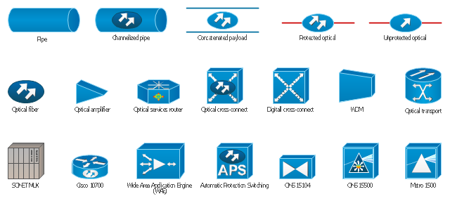
The vector stencils library "Cisco optical" contains 19 symbols of optical devices for drawing Cisco computer network diagrams.
"Fiber-optic communication is a method of transmitting information from one place to another by sending pulses of light through an optical fiber. The light forms an electromagnetic carrier wave that is modulated to carry information. ... Because of its advantages over electrical transmission, optical fibers have largely replaced copper wire communications in core networks in the developed world. Optical fiber is used by many telecommunications companies to transmit telephone signals, Internet communication, and cable television signals. ...
The process of communicating using fiber-optics involves the following basic steps: Creating the optical signal involving the use of a transmitter, relaying the signal along the fiber, ensuring that the signal does not become too distorted or weak, receiving the optical signal, and converting it into an electrical signal." [Fiber-optic communication. Wikipedia]
The symbols example "Cisco optical - Vector stencils library" was created using the ConceptDraw PRO diagramming and vector drawing software extended with the Cisco Network Diagrams solution from the Computer and Networks area of ConceptDraw Solution Park.
www.conceptdraw.com/ solution-park/ computer-networks-cisco
Automatic Protection Switching (APS)
-cisco-optical---vector-stencils-library.png--diagram-flowchart-example.png)
Channelized pipe

Concatenated payload

Optical cross-connect

WDM

Optical fiber

ONS 15104

SONET MUX

Optical amplifier

Digitall cross-connect

Optical services router

Cisco 10700

Optical transport

Wide Area Application Engine (WAE)
-cisco-optical---vector-stencils-library.png--diagram-flowchart-example.png)
Protected optical

Unprotected optical

Metro 1500

ONS 15500

Pipe

Network Glossary Definition

Easy to draw network topology diagrams, network mapping and Cisco network topology.
The vector stencils library "Cable TV" contains 64 symbols of cable TV network equipment.
Use these shapes for drawing CATV system design floor plans, network topology diagrams, wiring diagrams and cabling layout schemes in the ConceptDraw PRO diagramming and vector drawing software.
The vector stencils library "Cable TV" is included in the Electric and Telecom Plans solution from the Building Plans area of ConceptDraw Solution Park.
Use these shapes for drawing CATV system design floor plans, network topology diagrams, wiring diagrams and cabling layout schemes in the ConceptDraw PRO diagramming and vector drawing software.
The vector stencils library "Cable TV" is included in the Electric and Telecom Plans solution from the Building Plans area of ConceptDraw Solution Park.
Output Directional Tap 1
Output Directional Tap 2
Output Directional Tap 3
Output Directional Tap 4
Output Directional Tap 5
2-way Splitter
3-way Splitter
4-way Splitter
AC Power Block
Bond
Down Guy
Building Guy and Anchor
Rock Guy with Anchor
Down Guy with Anchor
Pole-to-Pole Guy
Sidewalk Down Guy with Anchor
Sidewalk Down Guy
Slack Span Messenger Wire
Tensioned Messenger Wire w/out cable
Tensioned Messenger Wire
Ground
Joint Usage (Power & Telephone Pole)
Joint Usgae Pole with Transformer
Strut
Tree Guy with Anchor
Push Brace (smaller pole in actual relative position)
Extension Arm
Built CATV Pole
Proposed CATV Pole
Directional Tap 1
Directional Tap 2
Manhole
Telephone Pole
Riser Pole
Vault Handheld
Fixed Equalizer
Fixed Flat Attenuators
Other Supporting Structures
Pedestal - Underground Routing
Power Pole
Direct Buried Underground Routing
Duct Line Underground Routing
Line Terminations
2-Way Optical Splice Location
3-Way Optical Splice Location
4-Way Optical Splice Location
> 4-Way Optical Splice Location
Optical Amplifier
Cable AC Power Combiner
Optical Fiber Cable
Optical Connector
Wavelength Demultiplexer
Wavelength Multiplexer
Optical Transmitter
Optical Transmitter
Optical Node
Optical Splitter
Headend (Signal Processing)
Node
Primary Hub
Secondary Hub
Coaxial Splice
Power Supply
Variable Equalizer
The vector stencils library "Transmission paths" contains 43 symbols of power transmission paths, electronic circuits, bus connectors and elbows, terminals, junctions, and concentrators.
Use it to annotate electrical diagrams, electronic schematics and circuit diagrams.
"A physical medium in data communications is the transmission path over which a signal propagates.
Many transmission media are used as communications channel.
For telecommunications purposes in the United States, Federal Standard 1037C, transmission media are classified as one of the following:
(1) Guided (or bounded) - waves are guided along a solid medium such as a transmission line.
(2) Wireless (or unguided) - transmission and reception are achieved by means of an antenna.
One of the most common physical medias used in networking is copper wire. Copper wire to carry signals to long distances using relatively low amounts of power. The unshielded twisted pair (UTP) is eight strands of copper wire, organized into four pairs.
Another example of a physical medium is optical fiber, which has emerged as the most commonly used transmission medium for long-distance communications. Optical fiber is a thin strand of glass that guides light along its length.
Multimode and single mode are two types of commonly used optical fiber. Multimode fiber uses LEDs as the light source and can carry signals over shorter distances, about 2 kilometers. Single mode can carry signals over distances of tens of miles.
Wireless media may carry surface waves or skywaves, either longitudinally or transversely, and are so classified.
In both communications, communication is in the form of electromagnetic waves. With guided transmission media, the waves are guided along a physical path; examples of guided media include phone lines, twisted pair cables, coaxial cables, and optical fibers. Unguided transmission media are methods that allow the transmission of data without the use of physical means to define the path it takes. Examples of this include microwave, radio or infrared. Unguided media provide a means for transmitting electromagnetic waves but do not guide them; examples are propagation through air, vacuum and seawater.
The term direct link is used to refer to the transmission path between two devices in which signals propagate directly from transmitters to receivers with no intermediate devices, other than amplifiers or repeaters used to increase signal strength. This term can apply to both guided and unguided media.
A transmission may be simplex, half-duplex, or full-duplex.
In simplex transmission, signals are transmitted in only one direction; one station is a transmitter and the other is the receiver. In the half-duplex operation, both stations may transmit, but only one at a time. In full duplex operation, both stations may transmit simultaneously. In the latter case, the medium is carrying signals in both directions at same time." [Transmission medium. Wikipedia]
The shapes example "Design elements - Transmission paths" was drawn using the ConceptDraw PRO diagramming and vector drawing software extended with the Electrical Engineering solution from the Engineering area of ConceptDraw Solution Park.
Transmission path symbols

This network layout floorplan example was drawn on the base of the picture "Ethernet cable layout" illustrating "UGA Technical Network Liaison Handbook" from the website of the University of Georgia.
[netinfo.uga.edu/ tnlhand/ landiag.gif]
"The Ethernet physical layer is the physical layer component of the Ethernet family of computer network standards.
The Ethernet physical layer evolved over a considerable time span and encompasses quite a few physical media interfaces and several magnitudes of speed. The speed ranges from 1 Mbit/ s to 100 Gbit/ s, while the physical medium can range from bulky coaxial cable to twisted pair and optical fiber. In general, network protocol stack software will work similarly on all physical layers.
10-gigabit Ethernet was already used in both enterprise and carrier networks by 2007, with 40 Gbit/ s and 100 Gbit/ s Ethernet ratified." [Ethernet physical layer. Wikipedia]
The network layout floorplan example "Ethernet cable layout" was created using the ConceptDraw PRO diagramming and vector drawing software extended with the Network Layout Floor Plans solution from the Computer and Networks area of ConceptDraw Solution Park.
Network layout floorplan

Cisco Optical. Cisco icons, shapes, stencils and symbols

"The Ethernet physical layer is the physical layer component of the Ethernet family of computer network standards.
The Ethernet physical layer evolved over a considerable time span and encompasses quite a few physical media interfaces and several magnitudes of speed. The speed ranges from 1 Mbit/ s to 100 Gbit/ s, while the physical medium can range from bulky coaxial cable to twisted pair and optical fiber. In general, network protocol stack software will work similarly on all physical layers.
10-gigabit Ethernet was already used in both enterprise and carrier networks by 2007, with 40 Gbit/ s and 100 Gbit/ s Ethernet ratified. ...
Many Ethernet adapters and switch ports support multiple speeds, using autonegotiation to set the speed and duplex for the best values supported by both connected devices. If auto-negotiation fails, a multiple-speed device will sense the speed used by its partner, but will assume half-duplex. A 10/ 100 Ethernet port supports 10BASE-T and 100BASE-TX. A 10/ 100/ 1000 Ethernet port supports 10BASE-T, 100BASE-TX, and 1000BASE-T." [Ethernet physical layer. Wikipedia]
The LAN equipment and cabling layout floorplan example "Ethernet local area network layout floor plan" was created using the ConceptDraw PRO diagramming and vector drawing software extended with the Network Layout Floor Plans solution from the Computer and Networks area of ConceptDraw Solution Park.
Ethernet LAN layout floorplan

The vector stencils library "Transmission paths" contains 43 symbols of power transmission paths, electronic circuits, bus connectors and elbows, terminals, junctions, and concentrators.
Use it to annotate electrical diagrams, electronic schematics and circuit diagrams in the ConceptDraw PRO diagramming and vector drawing software extended with the Electrical Engineering solution from the Engineering area of ConceptDraw Solution Park.
www.conceptdraw.com/ solution-park/ engineering-electrical
2-line bus

3-line bus 2

4-line bus

8-line bus

2-line bus elbow

3-line bus elbow 2

4-line bus elbow

8-line bus elbow

3-line bus

3-line bus elbow

4-line bus 2

8-line bus 2

4-line bus elbow 2

8-line bus elbow 2

Point

Terminal

Terminal 3-phase

Label

Flow direction, right
Flow direction, left
Flow direction, inward

Flow direction, outward
Transmission path

Line, overhead

Line, underground

Line, submarine

Line, loaded

Line, coaxial

Cable group

Lead group

Anticreep device

Line concentrator

Overground enclosure

Overground enclosure 2

Optical fiber

Optical fiber 2

Straight bus

Straight bus 2

Elbow bus

Elbow bus 2

Elbow bus 3

Elbow bus 4

Bus width

Internet Connectivity. Computer and Network Examples
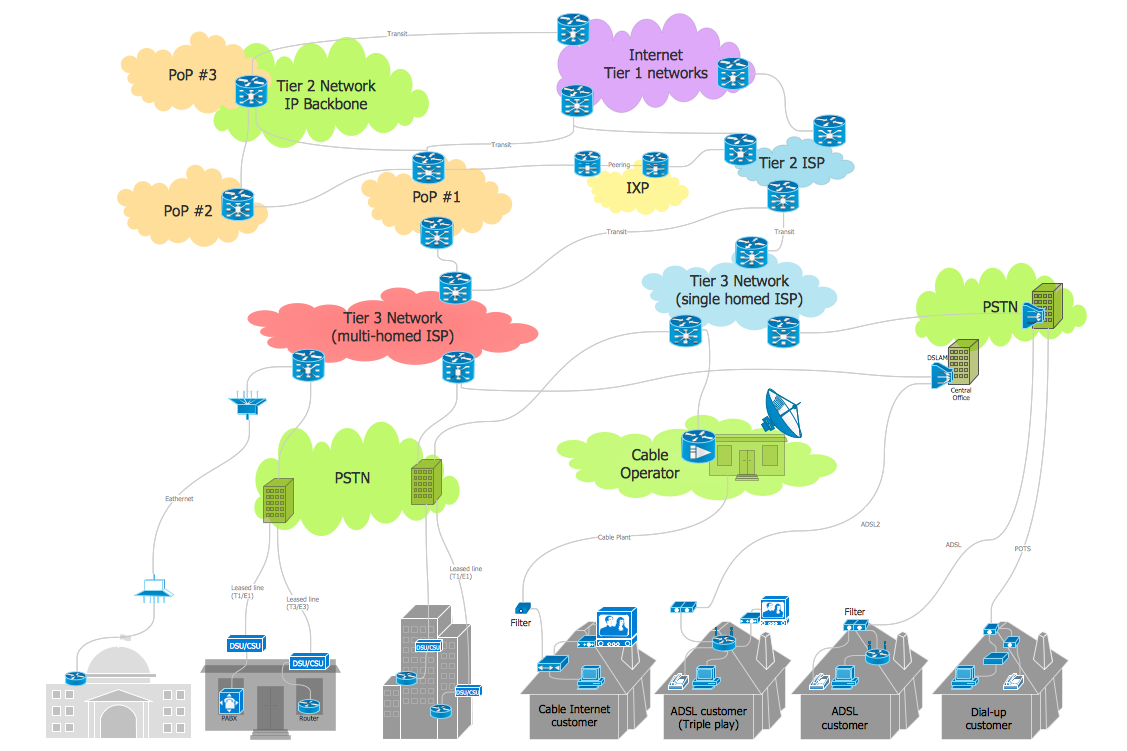
This example was created in ConceptDraw DIAGRAM using the Computer and Networks solution from the Computer and Networks area of ConceptDraw Solution Park and shows how the customers connect to ISPs and ISPs connect between the tiers (peering and transit).
The vector stencils library "Cisco optical" contains 19 symbols of optical devices: Automatic protection switching, Channelized pipe, Concatenated payload, Optical cross-connect, WDM, Optical fiber, ONS15104, SONET MUX, Optical amplifier, Digital cross-connect, Optical Services Router, Cisco 10700, Optical transport, Wide Area Application Engine (WAE), Protected optical, Unprotected optical, Metro 1500, ONS 15500, Pipe, Radio tower.
Create the computer network topology diagrams using the ConceptDraw PRO diagramming and vector drawing software with the design elements library "Cisco optical".
The example "Design elements - Cisco optical" is included in the Cisco Network Diagrams solution from the Computer and Networks area of ConceptDraw Solution Park.
Cisco optical symbols
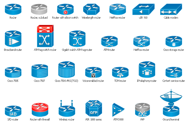
The vector stencils library "Cisco routers" contains 27 router symbols for drawing the Cisco computer network diagrams using the ConceptDraw PRO diagramming and vector drawing software.
"A router is a device that forwards data packets between computer networks, creating an overlay internetwork. A router is connected to two or more data lines from different networks. When a data packet comes in one of the lines, the router reads the address information in the packet to determine its ultimate destination. Then, using information in its routing table or routing policy, it directs the packet to the next network on its journey. Routers perform the "traffic directing" functions on the Internet. A data packet is typically forwarded from one router to another through the networks that constitute the internetwork until it reaches its destination node.
The most familiar type of routers are home and small office routers that simply pass data, such as web pages, email, IM, and videos between the home computers and the Internet. An example of a router would be the owner's cable or DSL modem, which connects to the Internet through an ISP. More sophisticated routers, such as enterprise routers, connect large business or ISP networks up to the powerful core routers that forward data at high speed along the optical fiber lines of the Internet backbone. Though routers are typically dedicated hardware devices, use of software-based routers has grown increasingly common." [Router (computing). Wikipedia]
The example "Design elements - Cisco routers" is included in the Cisco Network Diagrams solution from the Computer and Networks area of ConceptDraw Solution Park.
Cisco router symbols
The vector stencils library "Telecom" contains 20 telecommunication icons.
Use it to design your IT and telecom illustrations and infographics with ConceptDraw PRO diagramming and vector drawing software.
The vector stencils library "Telecom" is included in the Computers and Communications solution from the Illustration area of ConceptDraw Solution Park.
Use it to design your IT and telecom illustrations and infographics with ConceptDraw PRO diagramming and vector drawing software.
The vector stencils library "Telecom" is included in the Computers and Communications solution from the Illustration area of ConceptDraw Solution Park.
Call center

Support center

Hotline

Phone receiver

Digital phone
Cordless phone

Landline phone

Walkie Talkie

Police radio

Aviation

Base station
Communication tower

Dish antenna

Satellite

Global communication

Broadcasting

Active PC

Antenna TV

Transportation

Rocket

Digital Communications Network. Computer and Network Examples

This example was created in ConceptDraw DIAGRAM using the Computer and Networks Area of ConceptDraw Solution Park and shows the Digital Communication Network diagram.
Cisco Products Additional. Cisco icons, shapes, stencils and symbols

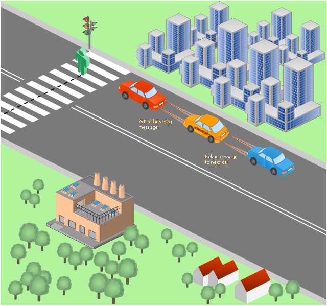
This vehicular network diagram sample was drawn on the base of picture illustrating the post "LED Traffic Signals and Vehicle Lights for Optical Broadband Communications" from the blog "Terranautix".
"Visible Light Communication (VLC) is a rapidly emerging field that focuses on the use of light sources (between 400 THz and 800 THz) for the primary purpose of broadband communications. In order to transmit data over light, the light source (transceiver) is pulsed on and off rapidly to create a data stream, similar to fiber optic communications, but in the wireless form, or “Free-Space Optical Transmission“. By pulsing lights many thousands (and millions) of times per second, data transmission occurs at a rate undetectable by the human eye. Optical receivers convert the light pulses to an electronic signal on the receiver end. The Light Emitting Diode (LED) is the primary form factor currently undergoing extensive research."
[terranautix.com/ tag/ communications]
The vehicular network diagram example "Visible light communication" was created using the ConceptDraw PRO diagramming and vector drawing software extended with the Vehicular Networking solution from the Computer and Networks area of ConceptDraw Solution Park.
Vehicular network diagram
Used Solutions
- Optical Fiber Symbol
- Cisco Optical . Cisco icons, shapes, stencils and symbols | Cisco ...
- Cable Network. Computer and Network Examples | Network ...
- Cisco Optical . Cisco icons, shapes, stencils and symbols | Cisco ...
- Cisco Optical . Cisco icons, shapes, stencils and symbols | Design ...
- Ethernet local area network layout floor plan | Design elements ...
- Network Diagram Software Physical Network Diagram | Physical ...
- Cable TV - Vector stencils library
- Network wiring cable . Computer and Network Examples | Network ...
- Optical Connector
- Design elements - Cable TV (CATV) | Regional cable head-end ...
- Design elements - Cable TV (CATV) | Cable TV - Vector stencils ...
- Cable TV - Vector stencils library
- Cable TV - Vector stencils library | Design elements - Valves ...
- Cable TV - Vector stencils library | Telecommunication networks ...
- Local network physical topology floor plan | ConceptDraw PRO ...
- Regional cable head-end diagram | Cable TV - Vector stencils ...
- Design elements - Cable TV (CATV)
- Cable TV - Vector stencils library | Design elements - Cable TV ...
- Electrical Drawing Symbols Of Tv Cable
- ERD | Entity Relationship Diagrams, ERD Software for Mac and Win
- Flowchart | Basic Flowchart Symbols and Meaning
- Flowchart | Flowchart Design - Symbols, Shapes, Stencils and Icons
- Flowchart | Flow Chart Symbols
- Electrical | Electrical Drawing - Wiring and Circuits Schematics
- Flowchart | Common Flowchart Symbols
- Flowchart | Common Flowchart Symbols