Electrical Diagram
Electrical Diagram is a visual graphical representation of an electrical circuit. ConceptDraw DIAGRAM diagramming and vector drawing software supplied with unique Electrical Engineering Solution from the Industrial Engineering Area will help you design Electrical Diagram of any complexity without efforts.

Example 1. Electrical Diagram - Simple Switched Supply
Electrical Symbols
First of all, the Electrical Engineering Solution provides a huge collection of ready-to-use predesigned elements. These are 926 electrical symbols grouped in 26 libraries:
- Analog and Digital Logic
- Composite Assemblies
- Delay Elements
- Electrical Circuits
- Electron Tubes
- IGFET
- Inductors
- Integrated Circuit
- Lamps, Acoustics, Readouts
- Logic Gate Diagram
- MOSFET
- Maintenance
- Power Sources
- Qualifying
- Resistors
- Rotating Equipment
- Semiconductor Diodes
- Semiconductors
- Stations
- Switches and Relays
- Terminals and Connectors
- Thermo
- Transformers and Windings
- Transistors
- Transmission Paths
- VHF UHF SHF
All these libraries and their samples are available from Electrical Engineering Solution section in ConceptDraw STORE.

Example 2. Electrical Symbols in ConceptDraw STORE
To design Electrical Diagram: create new ConceptDraw document, simply drag appropriate elements from the libraries to this document and arrange them in a desirable way.

Example 3. Electrical Diagram - Bipolar Current Mirror
The set of electrical diagram samples you see on this page was created in ConceptDraw DIAGRAM software using the tools of Electrical Engineering Solution. An experienced user spent 10-15 minutes creating each of these samples.
Use the Electrical Engineering Solution for ConceptDraw DIAGRAM software to create your own professional looking electrical diagram fast, easy and effective.
All source documents are vector graphic documents. They are available for reviewing, modifying, or converting to a variety of formats (PDF file, MS PowerPoint, MS Visio, and many other graphic formats) from the ConceptDraw STORE. The Electrical Engineering Solution is available for all ConceptDraw DIAGRAM or later users.
NINE RELATED HOW TO's:
You need design the Classroom Layout for the school, high-school, university? Now it's incredibly easy to do this in ConceptDraw DIAGRAM software which was supplied with School and Training Plans Solution from the Building Plans Area.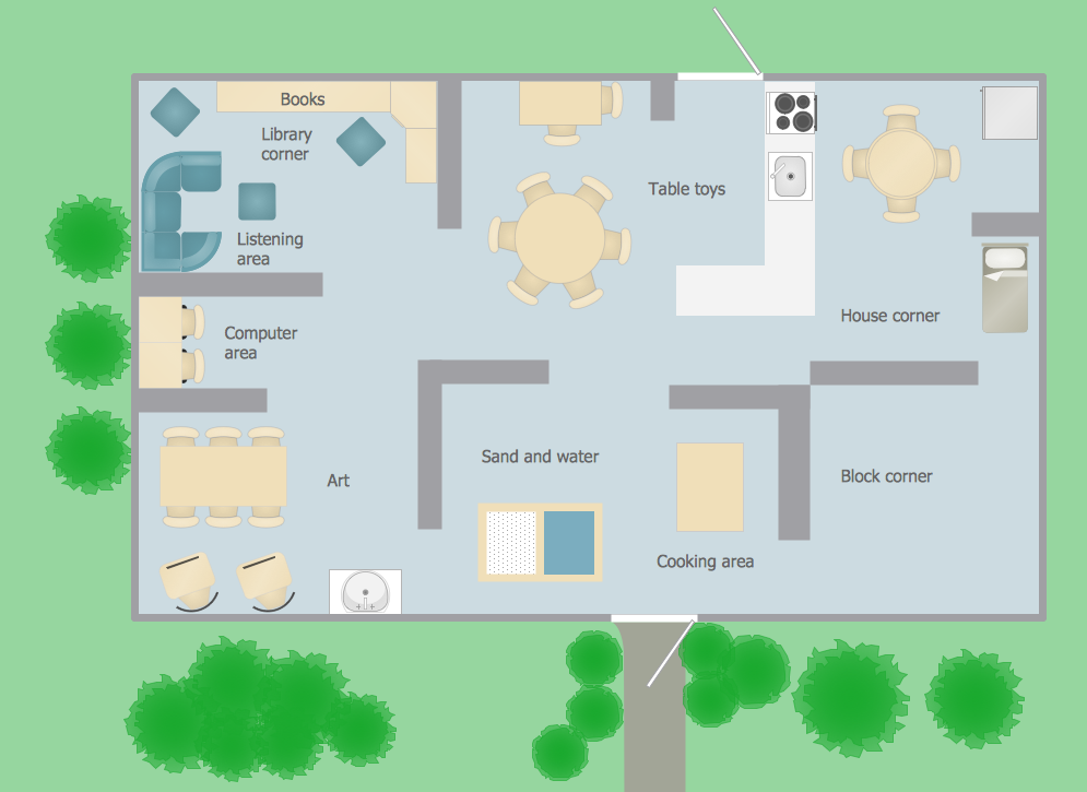
Picture: Classroom Layout
Related Solution:
This sample shows the Flowchart of the testing the work of the lamp and decision making about what to do to lamp will work.
Picture: Samples of Flowchart
Related Solution:
There are several types of insulated gate field-effect transistors (IGFETs) in common use.
The early term metal oxide semiconductor field-effect transistor (MOSFET) is still in
use, and MOSFET is usually acceptable as a generic term for IGFETs. The metal oxide, and the insulation in the IGFET, is the insulating material between the gate terminal and the substrate between the source and drain terminals. This insulator must have very low leakage, of course, but another requirement for good performance of the transistor is that the dielectric constant of the material must be very high.
26 libraries of the Electrical Engineering Solution of ConceptDraw DIAGRAM make your electrical diagramming simple, efficient, and effective. You can simply and quickly drop the ready-to-use objects from libraries into your document to create the electrical diagram.
Picture: Electrical Symbols — IGFET
Related Solution:
This template shows the restaurant floor plan for kids. The floor plans are necessary for architects, builders, designers. It’s very simple, convenient and quick to design the professional looking Floor Plans of any difficulty in ConceptDraw DIAGRAM.
Use the ready-to-use predesigned objects, templates and samples from the Floor Plans Solution for ConceptDraw DIAGRAM you can create your own Floor Plans quick and easy.
Picture: Template Restaurant Floor Plan for Kids
Related Solution:
Nodes of any computer network are somehow organized in a hierarchy or a layout. Some of the common layouts like star network topology are more reliable and some like ring topology withstand high loads better. It is also important to distinguish logical topologies from physical.
This diagram represents a typical view of the star network topology. The star network topology is one of the most frequently used network topologies in the majority of office and home networks. It is very popular because of its low cost and the easy maintenance. The plus of the star network topology is that if one computer on the local network is downed, this means that only the failed computer can not send or receive data. The other part of the network works normally. The minus of using star network topology is that all computers are connected to a single point-switch, or hub. Thus, if this equipment goes down, the whole local network comes down.
Picture: Star Network Topology
Related Solution:
ConceptDraw DIAGRAM is a powerful tool for drawing business communication ideas and concepts, simple visual presentation of numerical data in the Mac environment.
Picture: Best Multi-Platform Diagram Software
Related Solution:
Architectural drawing allows to show the location of a building or ensemble of buildings on the ground, indicating the cardinal points. For centuries, people had been studying architecture in universities to learn how to draw building plans and now everyone can do it easily just using appropriate software. While developing the building plan, its graphic part, you can display the part of the floor or the entire floor of a building with an indication of the exact location of the drawn premise.
Small-sized apartments does not restrict the advanced interior design opportunities. Here is a detailed and precise floor plan of a pretty small apartment. A furniture objects are added to show possible interior of this home. This plan can be used to help somebody with a floor layout and furniture arrangement. Having this floor plan in a pocket while shopping would be useful to check if there is enough rooms for a new furniture.
Picture: How To Draw Building Plans
Related Solution:

