Diagramming Software for Design
UML Object Diagrams
UML Object Diagrams Designing
UML Object Diagram shows the structure of a modeled system at a specific time. UML Object Diagram focuses on some particular set of object instances and attributes, and the links between the instances. A correlated set of object diagrams provides insight into how an arbitrary view of a system is expected to evolve over time.
ConceptDraw helps you to start designing UML Object Diagrams with examples and templates.
You can use the appropriate stencils of UML notation for drawing your own UML Object Diagram.
UML Object Diagram Library
ConceptDraw Rapid UML solution delivers libraries contain pre-designed objects fit UML notation, and ready to draw professional UML Object Diagram.

Example 1. UML Object Diagram library
UML Object Diagram Design Elements
Design elements sample shows all library objects at one page for quick review.

Example 2. UML Object Diagram design elements
Design UML Object Diagram in ConceptDraw DIAGRAM software
ConceptDraw DIAGRAM workspace is clear and simple. All tools you need for drawing UML Object Diagram are on hand.

Example 3. UML Object Diagram for Mac OS X

Example 4. UML Object Diagram for Windows
Examples of UML Object Diagram
This is an example of UML Object Diagram for an Safety inspection process.

Example 5. UML Object Diagram - Safety inspection
This UML object diagram sample is created using ConceptDraw DIAGRAM diagramming and vector drawing software enhanced with Rapid UML solution from ConceptDraw Solution Park.

Example 6. UML Object Diagram Solution
Rapid UML solution provides templates, examples and libraries of stencils for quick and easy drawing the all types of system and software engineering diagrams according to UML 2.4 notation.
Use ConceptDraw DIAGRAM with UML object diagram templates, samples and stencil library from Rapid UML solution to show the particular set of system objects, their attributes and the links between them.
NINE RELATED HOW TO's:
This sample shows the Flowchart that displays the solid-state welding processes, the types of welding.
Picture: Types of Welding in Flowchart
Related Solution:
Use the set of special professionally developed swim lane flowchart symbols - single, multiple, vertical and horizontal lanes from the Swimlanes and Swimlanes BPMN 1.2 libraries from the Business Process Diagram solution, the Swim Lanes library from the Business Process Mapping solution as the perfect basis for your Swim Lane Flowcharts of processes, algorithms and procedures.
Picture: Swim Lane Flowchart Symbols
Related Solution:
ConceptDraw DIAGRAM diagramming and vector drawing software is the best choice for making professional looking Emergency Plan template, examples and samples. ConceptDraw DIAGRAM provides Fire and Emergency Plans solution from the Building Plans Area of ConceptDraw Solution Park.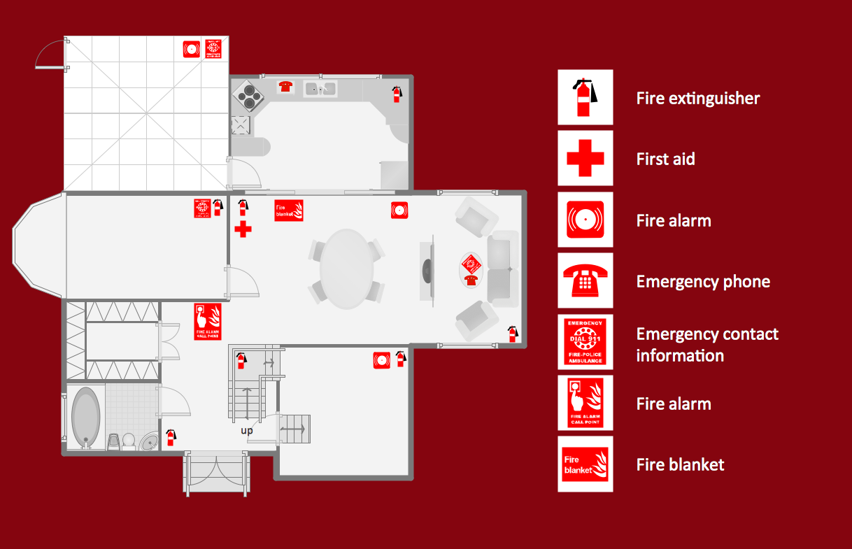
Picture: Emergency Plan Template
Related Solution:
This template shows the restaurant floor plan for kids. The floor plans are necessary for architects, builders, designers. It’s very simple, convenient and quick to design the professional looking Floor Plans of any difficulty in ConceptDraw DIAGRAM.
Use the ready-to-use predesigned objects, templates and samples from the Floor Plans Solution for ConceptDraw DIAGRAM you can create your own Floor Plans quick and easy.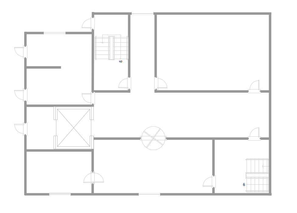
Picture: Template Restaurant Floor Plan for Kids
Related Solution:
ConceptDraw DIAGRAM creates drawings, diagrams and charts with great visual appeal in Mac OS X.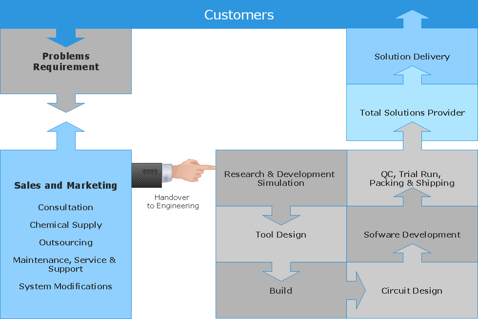
Picture: Best Vector Drawing Application for Mac OS X
Related Solution:
The Sales Process is a complex approach for selling a product or service which assumes many steps including the sales planning, realization of the sales marketing and management strategies, sales process analysis, etc. Now we have a ConceptDraw DIAGRAM software extended with unique Sales Flowcharts solution from the Marketing area of ConceptDraw Solution Park which ideally suits for the planning and realization the company's sales process.
Picture: The Sales Process
Related Solution:
When studying a business process or system involving the transfer of data, it is common to use a Data Flow Diagram (DFD) to visualize how data are processed. Being initially used exclusively in regards to the flow of data through a computer system, now DFDs are employed as the business modeling tools. They are applied to describe the business events and interactions, or physical systems involving data storage and transfer. ConceptDraw DIAGRAM is a powerful Data Flow Diagram software thanks to the Data Flow Diagrams solution from the Software Development area of ConceptDraw Solution Park.
Picture: Data Flow Diagram Software
Related Solution:


