Samples / Industrial Engineering / Power Circuits
Power Circuits
Sample power circuit diagrams in vector graphics format were created using ConceptDraw DIAGRAM diagramming and vector drawing software enhanced with free Power Circuits solution from the Industrial Engineering area.
ConceptDraw DIAGRAM can open and save documents that can be used by Visio (VSD, VDX, and VSDX files) users.
ConceptDraw DIAGRAM allows exporting of vector graphic multipage documents into multiple file formats: vector graphics (SVG, EMF, EPS), bitmap graphics (PNG, JPEG, GIF, BMP, TIFF), web documents (HTML, PDF), PowerPoint presentations (PPT), Adobe Flash (SWF).
Tutorials and Solutions:
Video Guides: Power Circuits
Solutions: Power Circuits for ConceptDraw DIAGRAM
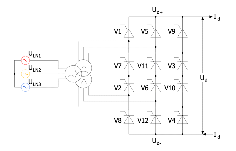
Sample 1: 12-Pulse Thyristor Rectifier Circuit
Power circuit diagram sample: This sample shows a simple twelve-pulse thyristor rectifier circuit diagram with YD11 transformer connected. The rectifier included in this circuit is an electrical device used to convert AC to DC. This means converting a periodically varying current into a current flowing strictly in one direction. A twelve-pulse bridge connection consists of two six-pulse bridge circuits and is often used with rectifiers. These two six-pulse bridges are connected in series.
This drawing is created using ConceptDraw DIAGRAM diagramming software enhanced with Power Circuits solution from ConceptDraw Solution Park.
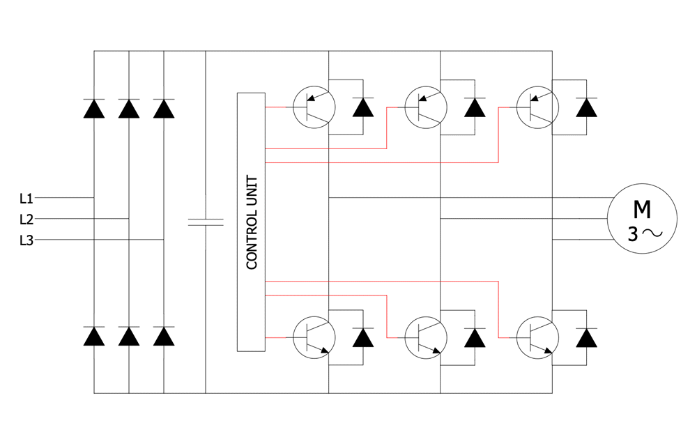
Sample 2: AC Chopper Electrical Circuit
Power circuit diagram sample: This sample shows an AC chopper electrical circuit. An AC chopper is a static power electronics device used as an AC converter. It is a highly demanded device owing to the fact that the current supplied to the load is often discontinuous.
This drawing is created using ConceptDraw DIAGRAM diagramming software enhanced with Power Circuits solution from ConceptDraw Solution Park.
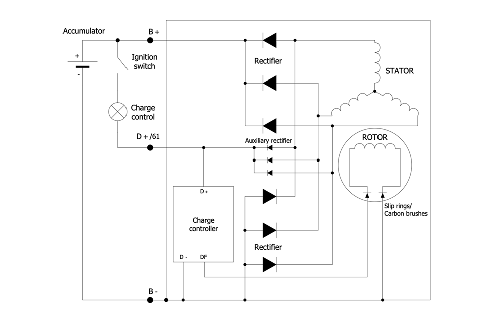
Sample 3: Alternator Circuit Diagram
Power circuit Diagram sample: This sample shows an alternator circuit diagram. The alternating current generating systems have been known since the 1830s when the magnetic induction of electric current was discovered. An alternator is an electric generator that converts mechanical energy to electrical energy in the form of AC. The modern alternators are used in automobiles to charge a battery and to power the electrical system at the running engine.
This drawing is created using ConceptDraw DIAGRAM diagramming software enhanced with Power Circuits solution from ConceptDraw Solution Park.
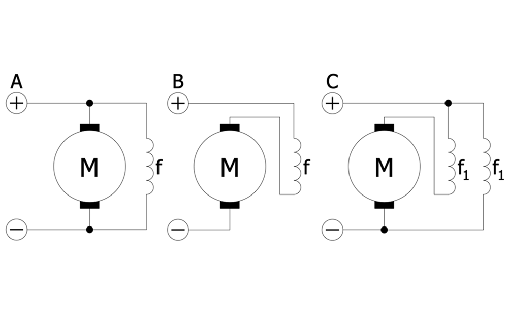
Sample 4: DC Machine Connections
Power circuit diagram sample: This sample shows the connector types for a DC machine. You can observe in detail how a field coil may be connected. There are three alternatives of electrical connections between the stator and rotor in DC electric machines (motors or generators): in shunt or parallel, in series, and in the compound. The compound connections join the previous two types in different combinations. Each of these types offers the unique characteristics of speed and torque.
This drawing is created using ConceptDraw DIAGRAM diagramming software enhanced with Power Circuits solution from ConceptDraw Solution Park.
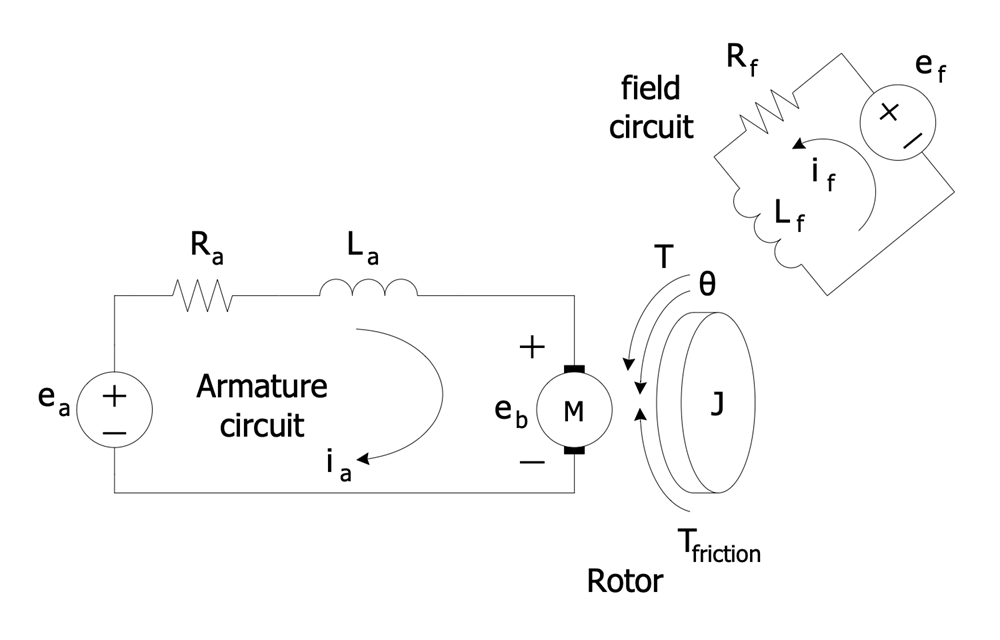
Sample 5: DC Motor with the Field and Armature Circuits
Power circuit diagram sample: This sample shows a simple DC motor with two circuits — field and armature. The field circuit is always a constant current. It flows in the excitation winding of a rotating electric machine and creates a magnetic field. In this case, the rotor winding acts as an excitation winding. The armature is the winding of an electric machine that carries an alternating current. It is a conductor or a conductive coil.
This drawing is created using ConceptDraw DIAGRAM diagramming software enhanced with Power Circuits solution from ConceptDraw Solution Park.
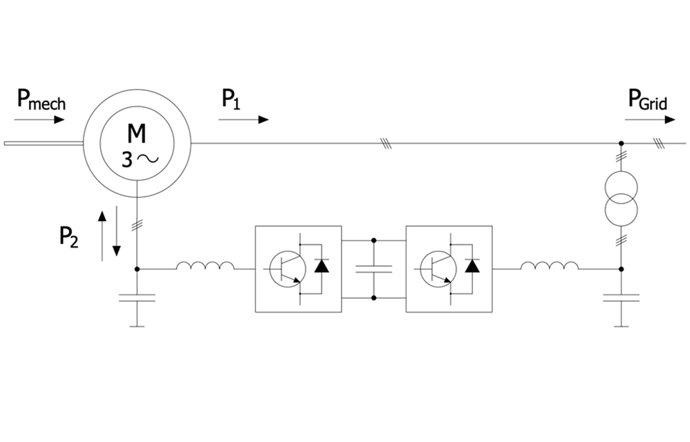
Sample 6: Double Fed Asynchronous Machine
Power circuit diagram sample: This sample shows a double-fed asynchronous machine. It is a type of electric motor or electric generator. The double-fed machine is similar to AC electrical generator but has some additional features. It runs at higher or lower speeds than its natural synchronous speed.
This drawing is created using ConceptDraw DIAGRAM diagramming software enhanced with Power Circuits solution from ConceptDraw Solution Park.
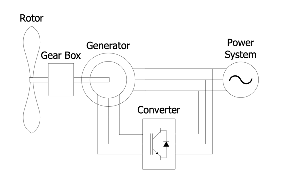
Sample 7: Double Fed Induction Generator Connected to a Wind Turbine
Power circuit diagram sample: This sample shows a Dual Powered Induction Generator (DFIG) connected to a wind turbine. The generators of this type are most commonly used, according to statistics about 80% of all worldwide used generators are DFIG. DFIG-based wind turbines possess the flexibility and ability to control active and reactive power. DFIG contains an induction generator with a multiphase wound rotor and a multiphase slip ring. The rotor windings are connected to the converter via slip rings and the stator ones are connected to the grid. The converter controls both the rotor and grid currents, and the stator's power fed to the grid. It controls the rotor field current frequency and the generator rotor speed.
This drawing is created using ConceptDraw DIAGRAM diagramming software enhanced with Power Circuits solution from ConceptDraw Solution Park.
All samples are copyrighted CS Odessa's.
Usage of them is covered by Creative Commons “Attribution Non-Commercial No Derivatives” License.
The text you can find at: https://creativecommons.org/licenses/by-nc-nd/3.0