Samples / Industrial Engineering / One-line Diagrams
One-line Diagrams
Sample schematic diagrams in vector graphics format depict the parts and devices composing the electrical systems and how incoming power is distributed to equipment. The examples of single-line diagrams were created using ConceptDraw DIAGRAM diagramming and vector drawing software enhanced with free One-line Diagrams solution from the Industrial Engineering area.
ConceptDraw DIAGRAM can open and save documents that can be used by Visio (VSD, VDX, and VSDX files) users.
ConceptDraw DIAGRAM allows exporting of vector graphic multipage documents into multiple file formats: vector graphics (SVG, EMF, EPS), bitmap graphics (PNG, JPEG, GIF, BMP, TIFF), web documents (HTML, PDF), PowerPoint presentations (PPT), Adobe Flash (SWF).
Tutorials and Solutions:
Video Guides: One-line Diagrams
Solutions: One-line Diagrams for ConceptDraw DIAGRAM
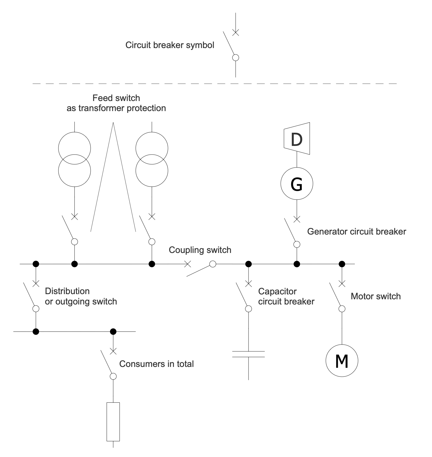
Sample 1: Application Examples of Circuit Breakers
One-line Diagram sample: This diagram shows examples of circuit breaker applications. A circuit breaker is a device for automatic switching of contacts (mechanical or electronic) capable of switching on, conducting and disconnecting currents in a circuit. It is used to protect an electrical circuit from damage caused by short circuit or overcurrent.
This drawing is created using ConceptDraw DIAGRAM diagramming software enhanced with One-line Diagrams solution from ConceptDraw Solution Park.
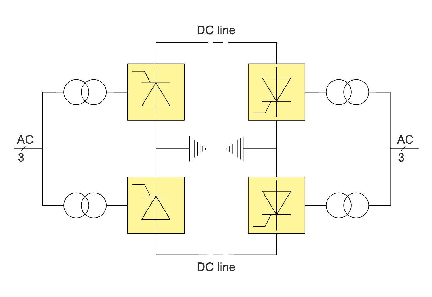
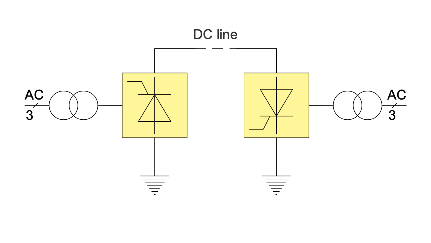
Sample: 2 One-Line Diagram — Bipolar HVDC
One-line Diagram sample: This Single-line Diagram sample shows the bipolar HVDC transmission system. This type of transmission has a lot of advantages when compared to monopole transmission. This circuit uses a pair of insulated conductors. They have opposite polarity, high ground potential and can operate as two parallel monopoles. AC is a designation for alternating current and DC line for the direct-current transmission line correspondingly.
This drawing is created using ConceptDraw DIAGRAM diagramming software enhanced with One-line Diagrams solution from ConceptDraw Solution Park.
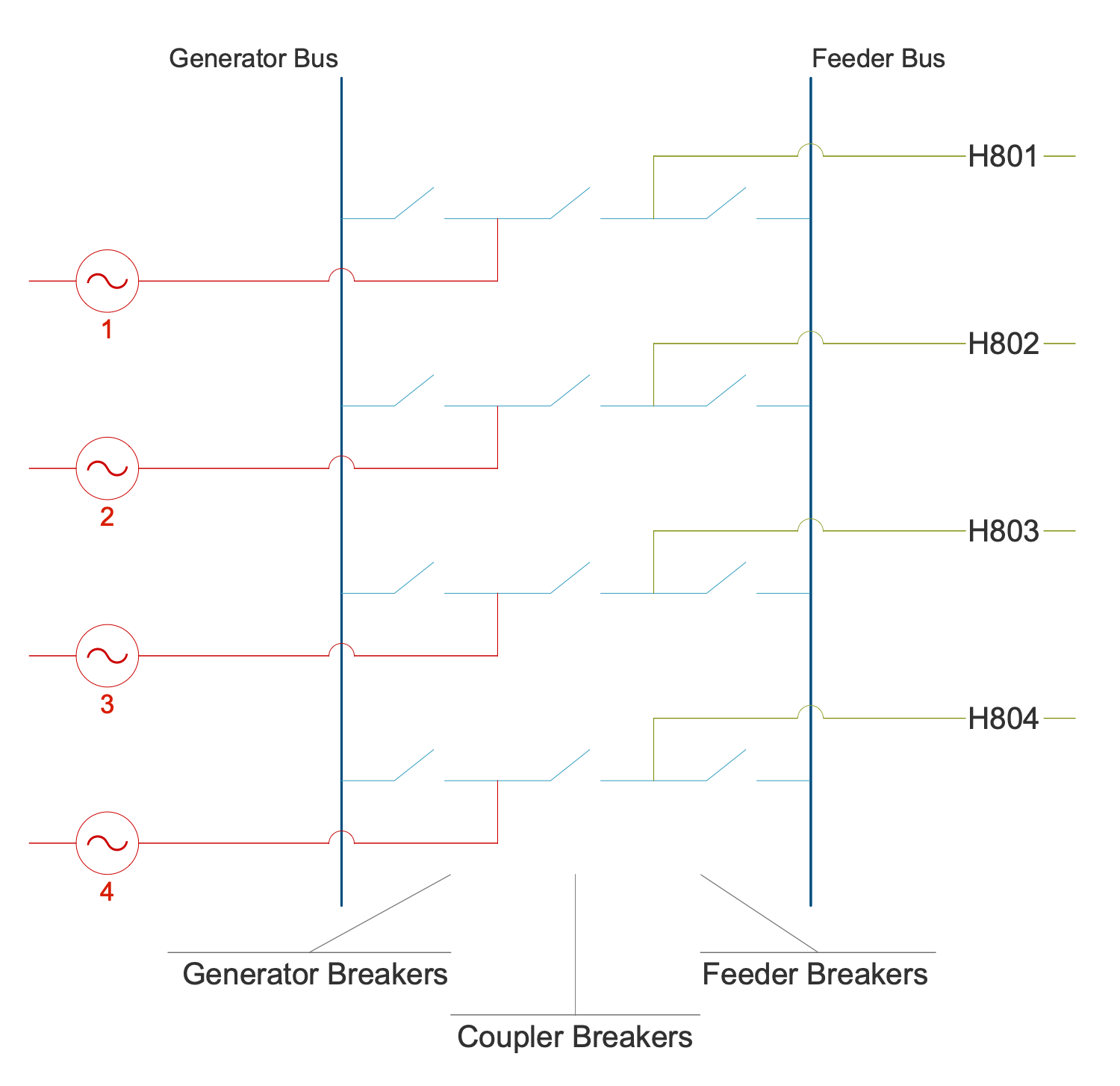
Sample 3: Breaker and a Half Switchyard Design Concept
One-line Diagram sample: This sample of One-line Diagram shows the breaker-and-a-half design concept used in switchyards. This configuration ensures that the failure of some circuit breakers does not interrupt power to other circuits. The One-line Diagram is obligatory to be constructed during planning a substation layout. Typically, it shows the arrangement of switching and protection equipment (switches, circuit breakers, transformers), incoming supply lines, outgoing feeders, transmission lines.
This drawing is created using ConceptDraw DIAGRAM diagramming software enhanced with One-line Diagrams solution from ConceptDraw Solution Park.
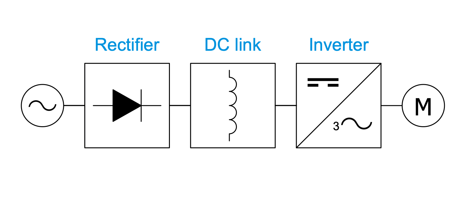
Sample 4: One-Line Diagram — Current Source Inverter
One-line Diagram sample: This One-line Diagram sample shows a topology of the current-source inverter (CSI) drive. It is also known as a current fed inverter because of its feeding with a constant current. CSI functions in closed-loop and isn't applied for multi-motor drives. CSI drive includes a rectifier, DC link, and inverter.
This drawing is created using ConceptDraw DIAGRAM diagramming software enhanced with One-line Diagrams solution from ConceptDraw Solution Park.
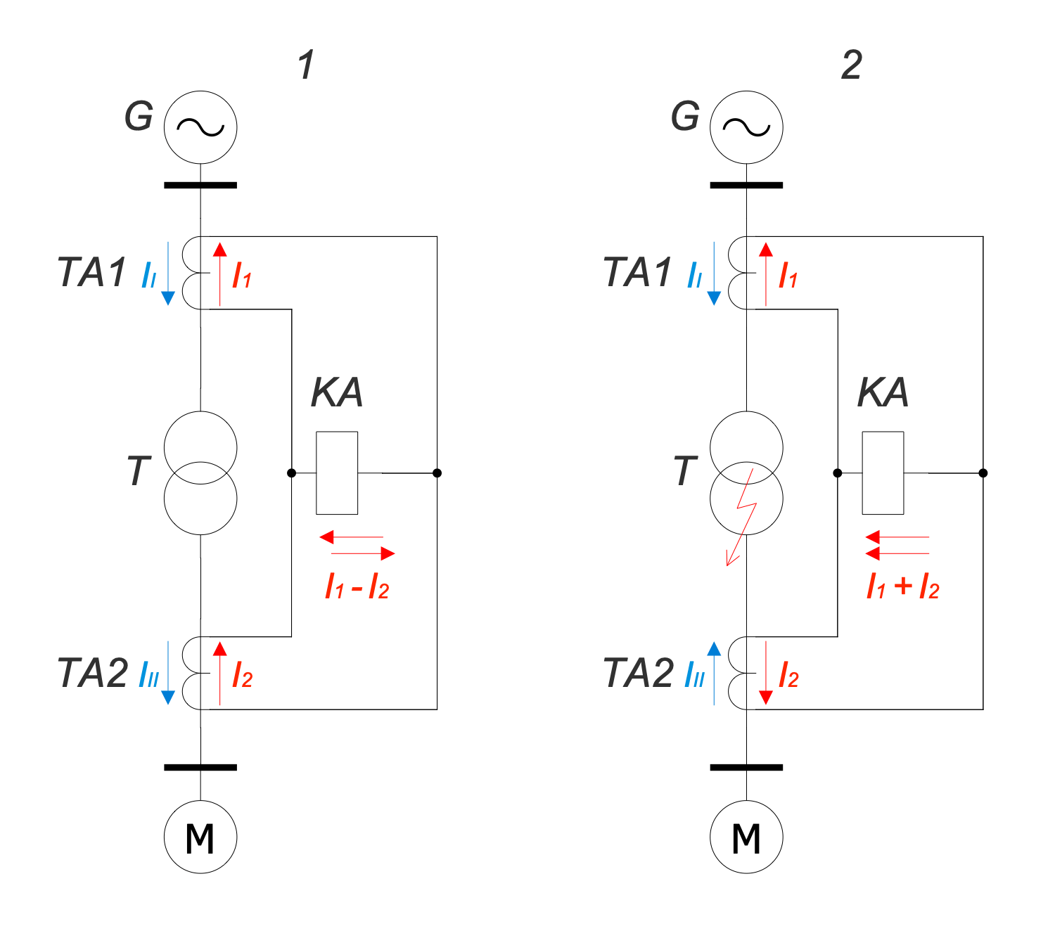
Sample 5: One-Line Diagram — Differential Protection
One-line Diagram sample: This sample of the One-line Diagram shows differential protection of the power transformer. Differential protection is one of the types of relay protection for transformers, autotransformers, generators, generator blocks, motors, overhead power lines, and busbars. It is characterized by absolute selectivity and high speed. The operating principle is based on the comparison of phase currents flowing through the sections between the protected line section. Two modes are displayed in a diagram — normal (1) and short circuit (2).
This drawing is created using ConceptDraw DIAGRAM diagramming software enhanced with One-line Diagrams solution from ConceptDraw Solution Park.
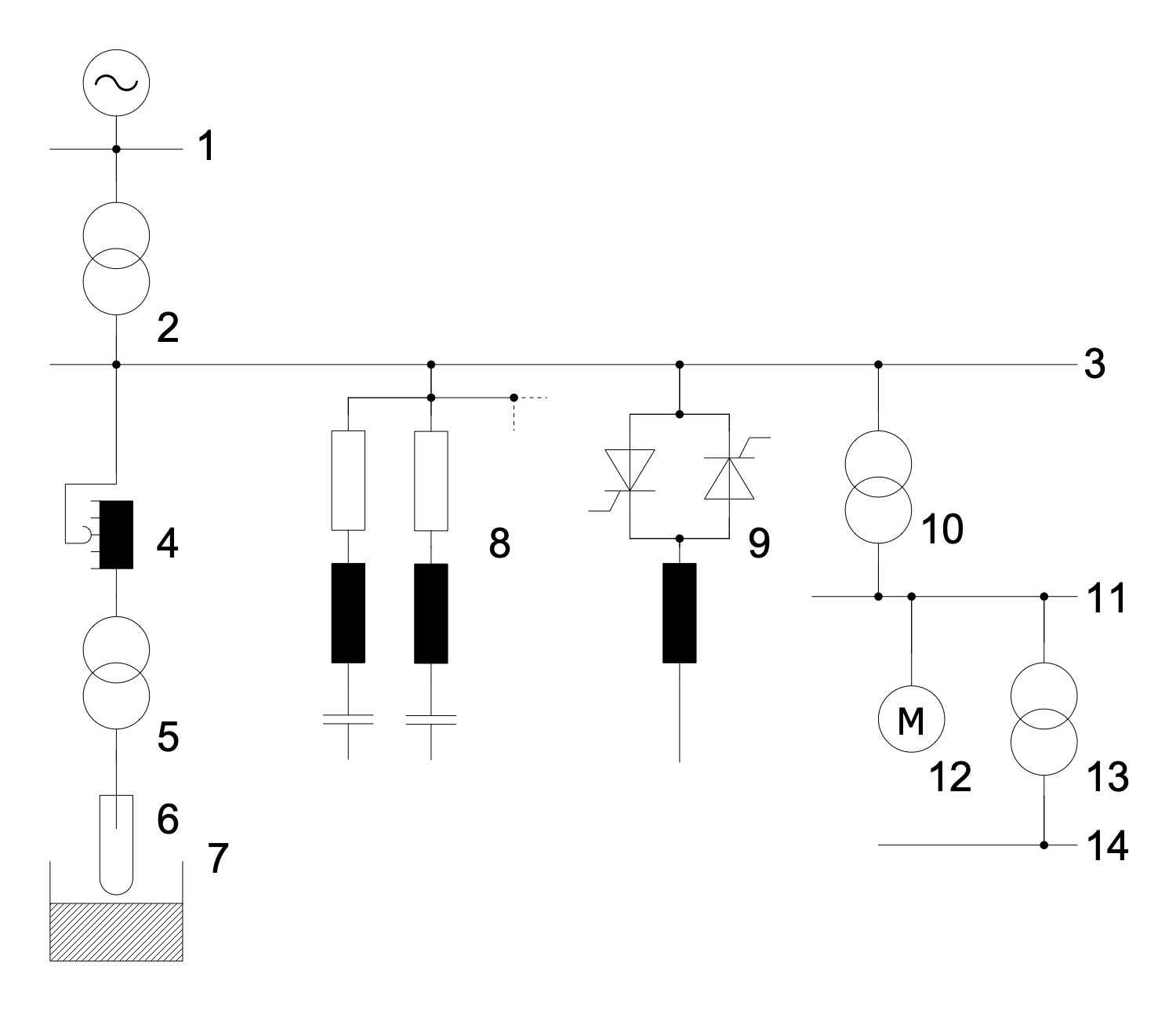
Sample 6: One-Line Diagram — Electric Arc Furnace Plant Network
One-line Diagram sample: This sample of one-line drawing shows an electrical on-site power grid in an electric arc furnace on a steel plant. An electric arc furnace (EAF) is a furnace using an electric arc to heat the materials. An electric arc affects the charged materials and the current from the furnace terminals passes through it.
This drawing is created using ConceptDraw DIAGRAM diagramming software enhanced with One-line Diagrams solution from ConceptDraw Solution Park.
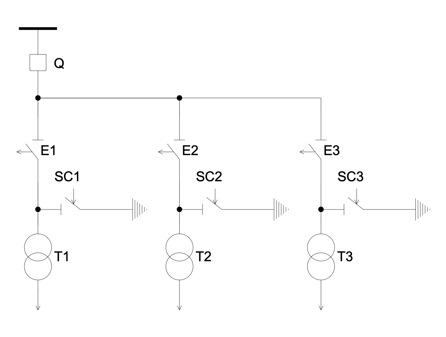
Sample 7: Electric Substation without High Voltage Switchgear
One-line Diagram sample: This electrical diagram shows an electrical substation without switches on the side. This substation includes three transformers (T1, T2, T3), three disconnectors (E1, E2, E3), three short circuit breakers (SC1, SC2, SC3) and a power line main switch (Q). In the event of an emergency on the line of one of the transformers, the protection installed on it supplies voltage to the switching coil of the corresponding short-circuit breaker.
This drawing is created using ConceptDraw DIAGRAM diagramming software enhanced with One-line Diagrams solution from ConceptDraw Solution Park.
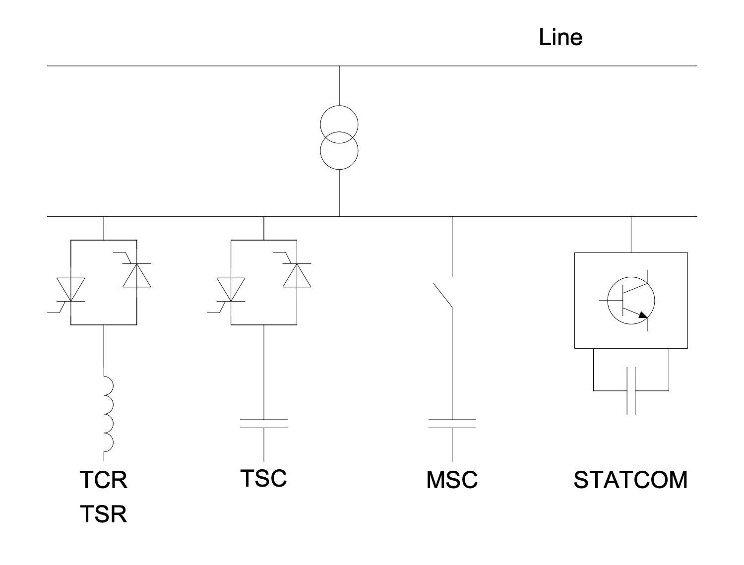
Sample 8: One-Line Diagram — FACTS Shunt Compensation
One-line Diagram sample: This sample shows examples of flexible alternating current transmission system (FACTS) for shunt compensation. FACTS enhances controllability and increases the power transfer capability of the network. It is a system including static equipment that uses an alternating current to transmit electrical energy. The shunt compensation supposes connection of the power system in shunt with the FACTS and operates as a controllable current source. Thyristor-controlled reactor (TCR), Thyristor-switched reactor (TSR), Thyristor-switched capacitor (TSC), Mechanically-switched capacitor (MSC), and Static synchronous compensator (STATCOM) are the examples.
This drawing is created using ConceptDraw DIAGRAM diagramming software enhanced with One-line Diagrams solution from ConceptDraw Solution Park.
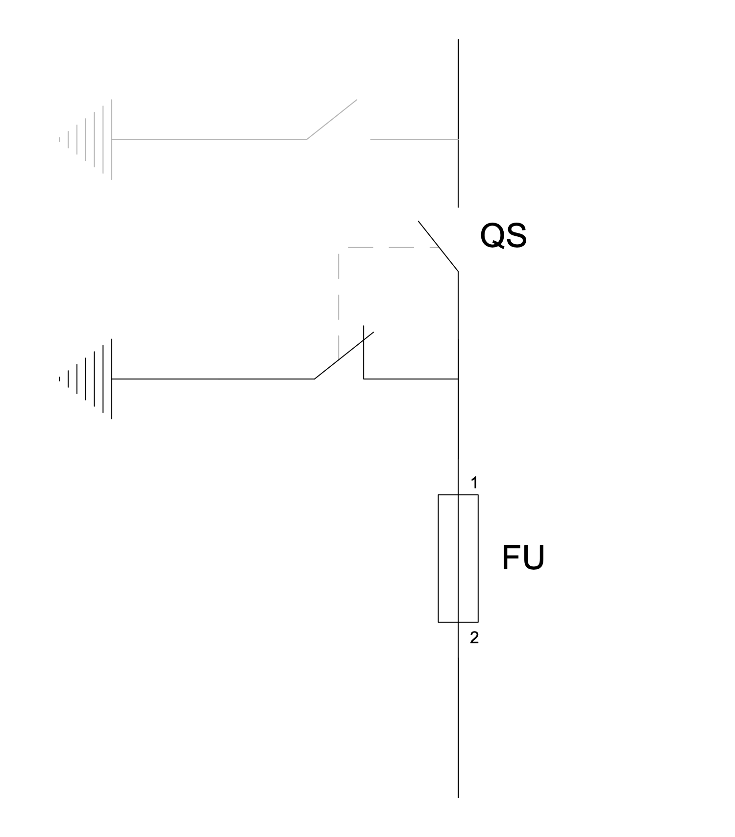
Sample 9: One-Line Diagram — Grounding Knifes
One-line Diagram sample: This sample shows a schematic of protection against the accidental return of voltage. It shows how to turn off the power in a distribution substation. According to the safety rules at the distribution substation, the grounding knifes must be obligatory launched into the ground before starting work. Two hot wires are used in USA and three in Europe. The diagram shows how to completely de-energize them for service or maintenance. The de-energizing is realized by means of a disconnector, disconnect switch, or isolator switch.
This drawing is created using ConceptDraw DIAGRAM diagramming software enhanced with One-line Diagrams solution from ConceptDraw Solution Park.
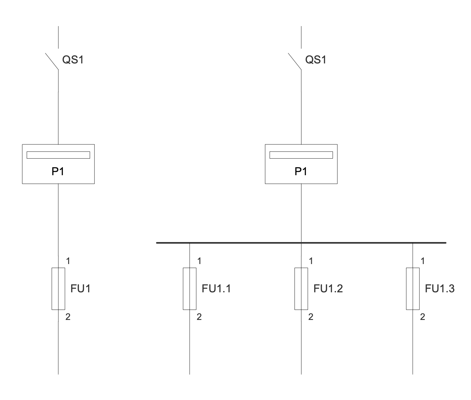
Sample 10: One-Line Diagram — Low Power Electricity Meter
One-line Diagram sample: This diagram shows an example of installing low-power (<80A) electricity meters. An electricity meter is a device used to measure the total amount of electricity consumed over a period of time. Induction single- and three-phase meters are used to account for active AC electricity. The movable part rotates during the consumption of electricity, and the counting mechanism takes into account its amount.
This drawing is created using ConceptDraw DIAGRAM diagramming software enhanced with One-line Diagrams solution from ConceptDraw Solution Park.
Sample 11: One-Line Diagram — Monopolar HVDC
One-line Diagram sample: This engineering diagram sample shows a monopolar high-voltage, direct current (HVDC) electric power transmission system with a ground return. In common, HVDC electric power transmission system uses direct current (DC) to transmit electrical power. It can also provide power transmission between non-synchronized AC transmission systems or grid systems operating at different frequencies. Sometimes monopolar systems are further used as a part of bipolar systems. In a monopolar system, the electrode line permanently carries the same current as the high-voltage conductor.
This drawing is created using ConceptDraw DIAGRAM diagramming software enhanced with One-line Diagrams solution from ConceptDraw Solution Park.
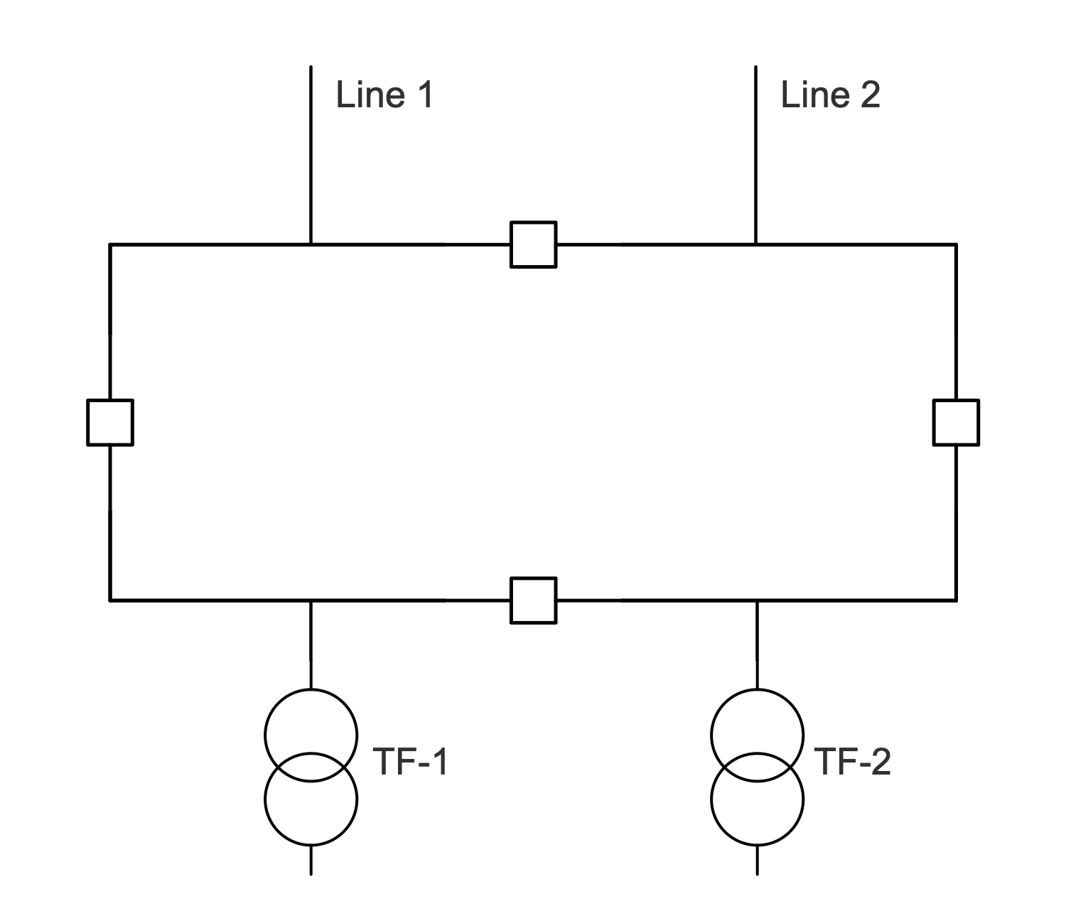
Sample 12: One-Line Diagram — Ring Bar Configuration
One-line Diagram sample: This one-line diagram sample shows an electrical ring bus bar configuration. This configuration is used for electric power distribution inside switchgear, panel boards, busway enclosures. In addition, it allows low voltage equipment to be connected to batteries and high voltage equipment to switchgear. Ring bus systems are usually not isolated and have many advantages. Two lines are included. The starting and endpoints of the bus bar are connected together with the help of a ring. The circuit of the ring bus bar system has two parallel paths.
This drawing is created using ConceptDraw DIAGRAM diagramming software enhanced with One-line Diagrams solution from ConceptDraw Solution Park.
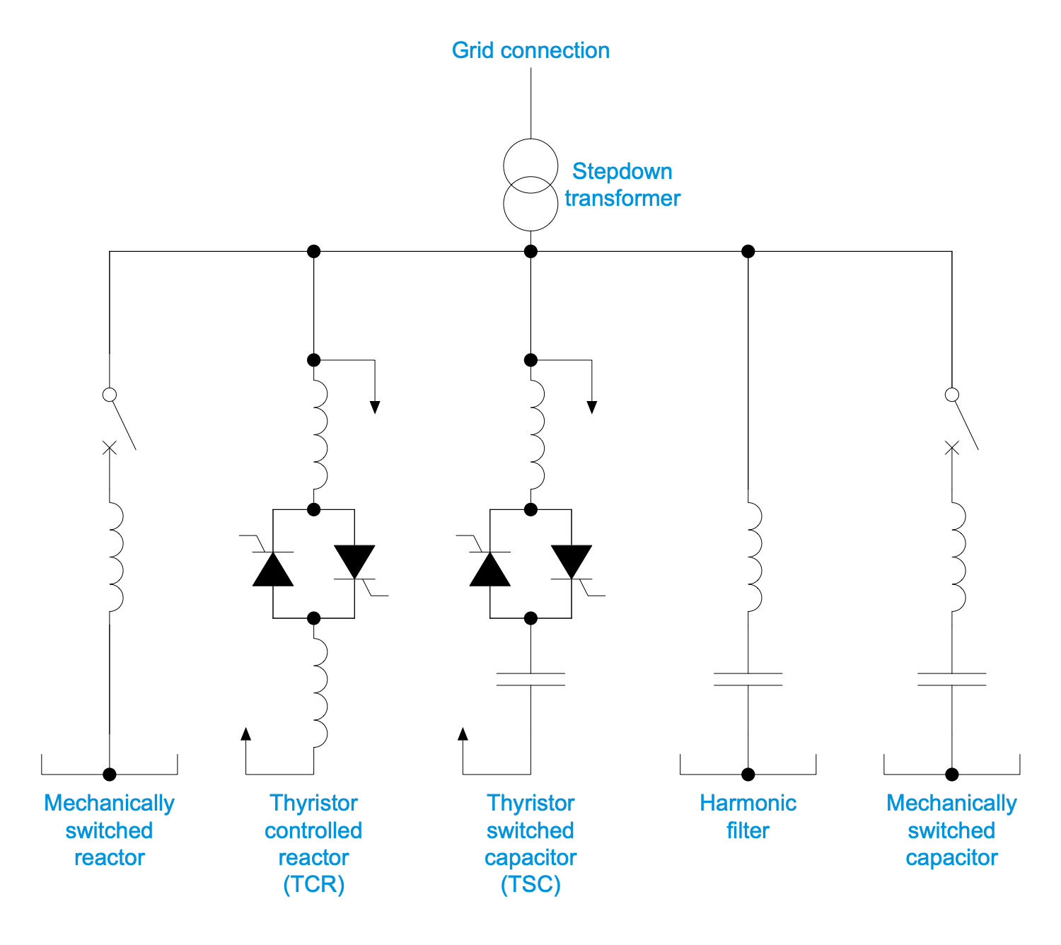
Sample 13: One-Line Diagram — Static VAR Compensator
One-line Diagram sample: This sample shows a typical transmission static VAR сompensator (SVC). It has no significant moving parts except the internal switchgear. The SVC provides high-speed reactive power in high voltage transmission networks, voltage regulation, and system stabilization. A distinctive feature of static VAR сompensators is their ability to support the voltage changes in the system, their response to them is almost instant. SVC includes a set of electrical devices including thyristor controlled reactor (TCR), thyristor switched capacitor (TSC), harmonic filter, mechanically switched capacitor, mechanically switched reactor, grid connection, and stepdown transformer.
This drawing is created using ConceptDraw DIAGRAM diagramming software enhanced with One-line Diagrams solution from ConceptDraw Solution Park.
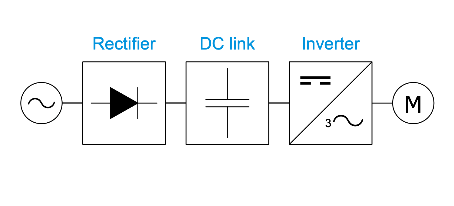
Sample 14: One-Line Diagram — Voltage Source Inverter Topology
One-line Diagram sample: This example shows a voltage source inverter (VSI) drive topology. Most drives are VSI type with PWM output voltage. VSI is a conventional power inverter used to convert DC voltage to AC voltage with variable value and frequency. The output voltage at VSI is constant. A voltage source inverter (VSI) topology is one of the typical topologies. The VSI drive consists of a rectifier, a DC link and a converter.
This drawing is created using ConceptDraw DIAGRAM diagramming software enhanced with One-line Diagrams solution from ConceptDraw Solution Park.
All samples are copyrighted CS Odessa's.
Usage of them is covered by Creative Commons “Attribution Non-Commercial No Derivatives” License.
The text you can find at: https://creativecommons.org/licenses/by-nc-nd/3.0