HelpDesk
How to Create a House of Quality Diagram

How To use House Electrical Plan Software


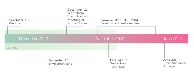
This sample was created on the base of the figure illustrating the webpage "SmartAmerica Challenge Timeline" from the website of the National Institute of Standards and Technology (NIST), an agency of the U.S. Department of Commerce. [nist.gov/ el/ sactl.cfm]
"The SmartAmerica Challenge is a White House Presidential Innovation Fellow project with the goal to bring together research in Cyber-Physical Systems (CPS) and to combine test-beds, projects and activities from different sectors, such as Smart Manufacturing, Healthcare, Smart Energy, Intelligent Transportation and Disaster Response, to show tangible and measurable benefits to the US economy and the daily lives of American citizens.
Cyber-Physical Systems is a name for the combination of the Internet of Things and System Control. So rather than just being able to “sense” where something is, CPS adds the capability to control the “thing” or allow it to interact with physical world around it.
Over 65 Companies, Government Agencies and Academic institutions came together on December 12, 2013 and launched 12 teams/ projects. Since that time 12 new projects have been formed. These teams have been hard at work over the past months building systems, prototypes, pilots and products that demonstrate the capabilities of CPS, but more importantly as the goal of the SmartAmerica Challenge they will show how these technologies will deliver socio-economic benefits to America.
The Challenge will culminate with the SmartAmerica Expo on June 11 at the Washington DC Convention Center." [smartamerica.org/ about/ ]
The timeline diagram example "" was created using the ConceptDraw PRO diagramming and vector drawing software extended with the Timeline Diagrams solution from the Management area of ConceptDraw Solution Park.
Timeline diagram
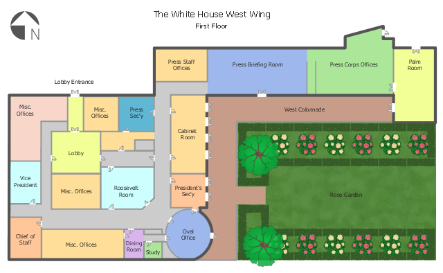
This architectural drawing sample was designed on the base of the Wikimedia Commons file: White House West Wing - 1st Floor.png.
"A floorplan of the first floor of the West Wing of the White House. Note that, depending on the administration, some positions (V.P., Chief of Staff, etc.) may be located in different offices than are shown here."
[commons.wikimedia.org/ wiki/ File:White_ House_ West_ Wing_ -_ 1st_ Floor.png]
"The West Wing of the White House, also known as the Executive Office Building, houses the offices of the President of the United States. The West Wing contains the Oval Office, the Cabinet Room, the Situation Room, and the Roosevelt Room.
The West Wing's three floors contain offices for the White House Chief of Staff, the Counselor to the President, the Senior Advisor to the President, the White House Press Secretary, and their support staffs. The Vice-President has an office in the building, but his primary office is next door in the Eisenhower Executive Office Building." [West Wing. Wikipedia]
The architectural drawing example "White House West Wing - 1st floor" was created using the ConceptDraw PRO diagramming and vector drawing software extended with the Floor Plans solution from the Building Plans area of ConceptDraw Solution Park.
Architectural drawing
 Floor Plans
Construction, repair and remodeling of the home, flat, office, or any other building or premise begins with the development of detailed building plan and floor plans. Correct and quick visualization of the building ideas is important for further construction of any building.
Home Architect Software. Home Plan Examples

Guesthouse Network. WIFI network to my guest house

Hotel Network Topology Diagram. Hotel Guesthouse WiFi Network

House of Quality Matrix Software

UML Block Diagram

- White House West Wing - 1st floor | Floor Plans | Food Court ...
- Network Layout Floor Plans | First Floor Electrical Drawing
- Floor Plans | Bubble diagrams with ConceptDraw PRO | School and ...
- How To use House Plan Software | How To use House Electrical ...
- Social Media Response | Wire Diagram Health Care
- Cable Layout Diagram Sample
- | SmartAmerica Challenge - Timeline | Network Security Diagrams ...
- How To use House Electrical Plan Software | Network Layout Floor ...
- Black And White Erd Diagram