The vector stencils library "Analog and digital logic" contains 40 element symbols of logic (threshold) gates, bistable current switches, current controllers, regulators, electrical generators, and amplifiers.
Use it for drawing the digital and analog functions in electronic circuit diagrams and electrical schematics in the ConceptDraw PRO diagramming and vector drawing software extended with the Electrical Engineering solution from the Engineering area of ConceptDraw Solution Park.
www.conceptdraw.com/ solution-park/ engineering-electrical
Clock
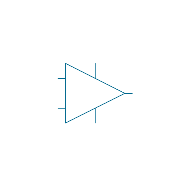
Function generator
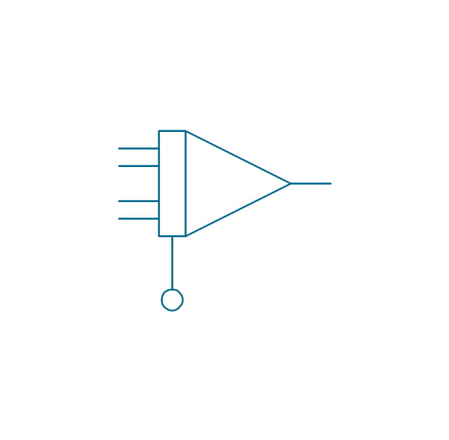
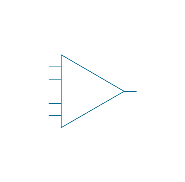
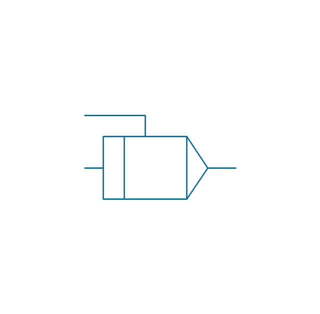
Amplifier
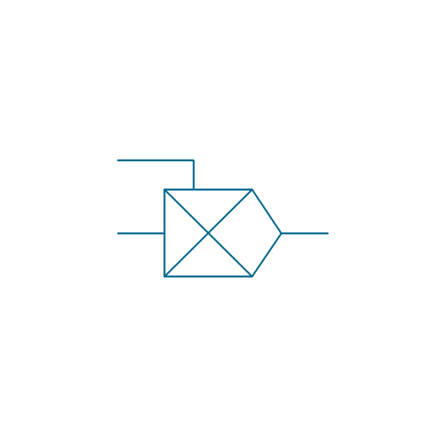
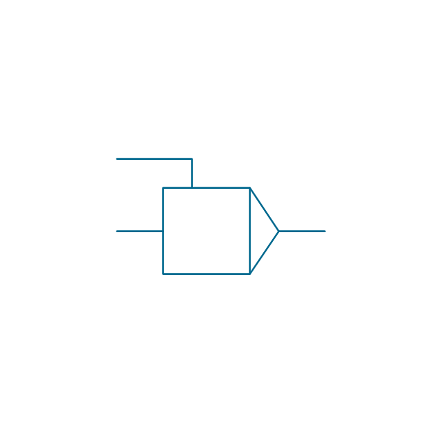
Converter
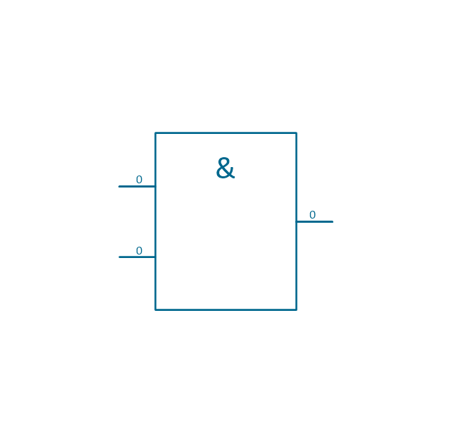
Logic gates
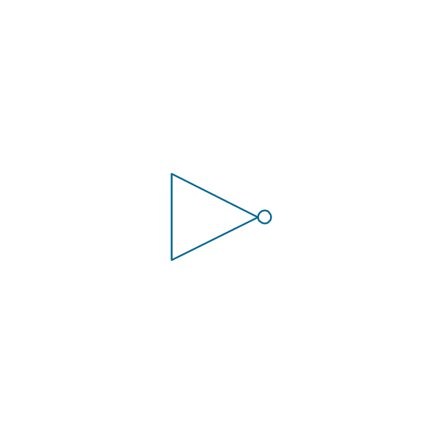
Inverter
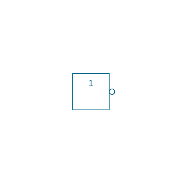
Inverter 2
Buffer

Buffer 2

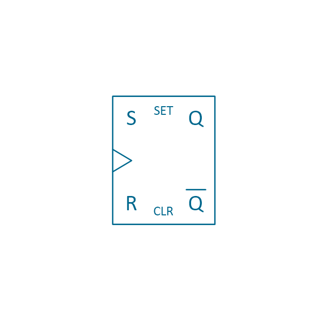
RS Flip-flop
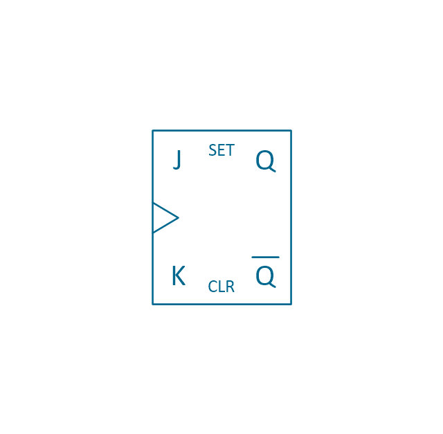
JK Flip-flop
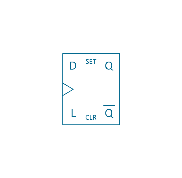
Latch Flip-flop
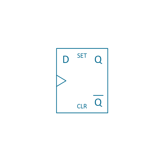
D Flip-flop
Analog symbol

Digital symbol

Negative logic dot

Potentiometer
Potentiometer 2
Positional servo
Piezoelectric crystal, 4 electrodes

Piezoelectric crystal, 3 electrodes

Piezoelectric crystal, 2 electrodes

I/O port bidirectional
I/O port unidirectional
Square signal

Sine wave signal
Sawtooth signal

Ramp signal
3 state data signal
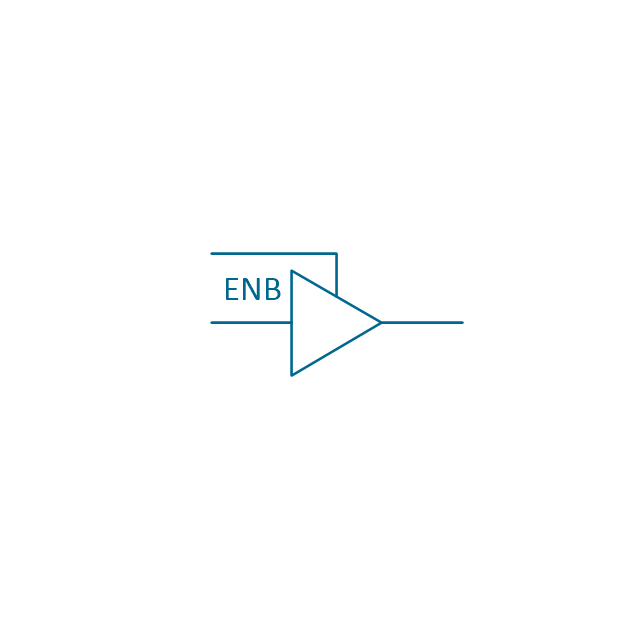
Three-state buffer
Integrator
Summing amplifier
Multiplier
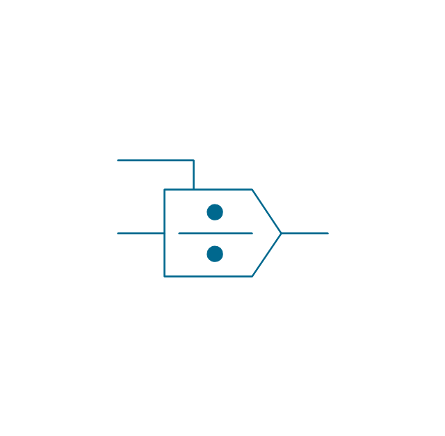
Divider
Function generator 2
Generalized integrator
Operational amplifier

Operational amplifier 2
Switch point
Switch point 2
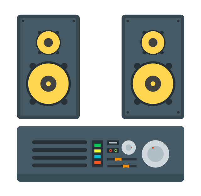
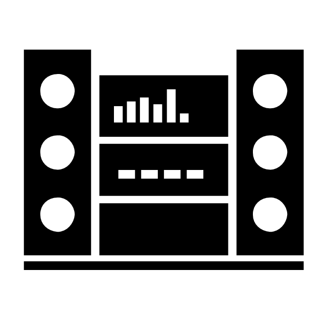
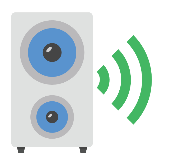
The vector stencils library "Audio" contains 91 audio, sound and music icons. Use it to design your audio, video and multimedia illustrations, presentations, web pages and infographics with ConceptDraw PRO diagramming and vector drawing software.
"Digital audio refers to technology that can be used to record, store, generate, manipulate, and reproduce sound using audio signals encoded in digital form. Following significant advances in digital audio technology during the 1970s, it rapidly replaced analog audio technology in most areas of sound production, sound engineering and telecommunications. Sound is converted to an analog electrical signal by a microphone, then an analog-to-digital converter (ADC), typically using pulse-code modulation, is used to convert it to a digital signal. A digital-to-analog converter performs the reverse process, converting a digital signal back into an analog signal, which can be converted to an audible sound by a loudspeaker. Digital audio systems may include compression, storage, processing and transmission components. Conversion to a digital format allows convenient manipulation, storage, transmission and retrieval of an audio signal." [Digital audio. Wikipedia]
The vector stencils library "Audio" is included in the Audio, Video, Media solution from the Illustration area of ConceptDraw Solution Park.
Audio wave

Mute

Volume

Music

Note

Notes

Music keys

Piano

Acoustic guitar

Guitar 1

Guitar 2

Electric guitar

Violin

Gramophone

Trumpet

Accordion

Microphone 1

Microphone 2

Microphone 3

Microphone 4

Microphone 5

Turn off microphone

Wire microphone

Mic 1

Mic 2

Karaoke

Singer

Megaphone 1

Megaphone 2

Loudspeaker

Bluetooth earpiece

Headset ear hook

Earphones 1

Earphones 2

Headset 1

Headset 2

Headset 3

Headphones 1

Headphones 2

Headphones 3

Headphones 4

Music player

Audio system

Stereo music system
Music system

Home theatre 1

Home theatre 2
Amplifier 1

Amplifier 2

Loudspeaker 1

Loudspeaker 2

Loudspeaker sound waves

Speaker 1

Speaker 2

Speaker box

Woofer

Woofer speaker
Subwoofer 1

Subwoofer 2

Stereo

Sound control
Vinyl

Audio cassette 1

Audio cassette 2

Cassette

Audio tape

Turntable

Record player

Cassette player
Tape player

Boombox 1

Boombox 2

Boombox 3

Portable radio

Radio set
Radio 1

Radio 2
Mixer
Equalizer 1

Equalizer 2
Equalizer 3
Volume adjuster
Volume control
DJ

Mixer table

Midi
Piano keyboard

Audio file

Music album

Audio cable 1

Audio cable 2

The vector stencils library "Computers and network isometric" contains 56 3D clipart images of computer and network devices and equipment for drawing network diagrams.
The clip art example "Computers and network isometric - Vector stencils library" was created using the ConceptDraw PRO diagramming and vector drawing software extended with the Computer and Networks solution from the Computer and Networks area of ConceptDraw Solution Park.
The clip art example "Computers and network isometric - Vector stencils library" was created using the ConceptDraw PRO diagramming and vector drawing software extended with the Computer and Networks solution from the Computer and Networks area of ConceptDraw Solution Park.
Laptop

DDCS

Server

Webcam

Wireless Network Storage

Personal computer

VoIP phone

Fax

Plotter

Mobile phone

Feature phone

Printer

Satellite dish

Satellite antenna

Automatic-tracking satellite dish
Wireless access point

Wireless router

Router

Network switch

Network device

Mobile GPS Terminal

GPS phone

Television antenna

Radio tower

Base station

Satellite

In-vehicle satellite telecommunication

Satellite dishes on ship

Airplane

Internet

Man

Woman

Call-center

Honeycomb

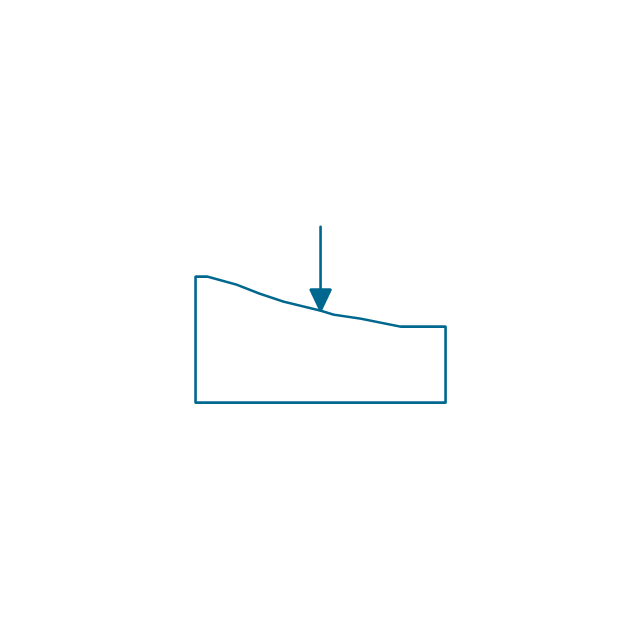
Mountain

Radio waves

Radio waves

Tower block

Office building

House

House

Globe

Wireless security camera

Truck

Tree

Conifer tree

1U hub / switch

2U hub / switch

1U server

2U Server

3U Server

4U Server

Communications satellite

Car

Radio waves

Firewall

The vector stencils library "VHF UHF SHF" contains 52 symbols for VHF, UHF, and SHF circuit design, including capacitance measurers, nonreciprocal devices, modulators, phase shifters, field polarization devices, and filters.
"Very high frequency (VHF) is the ITU-designated range of radio frequency electromagnetic waves from 30 MHz to 300 MHz, with corresponding wavelengths of one to ten meters. Frequencies immediately below VHF are denoted high frequency (HF), and the next higher frequencies are known as ultra high frequency (UHF).
Common uses for VHF are FM radio broadcasting, television broadcasting, land mobile stations (emergency, business, private use and military), long range data communication up to several tens of kilometres with radio modems, amateur radio, and marine communications. Air traffic control communications and air navigation systems (e.g. VOR, DME & ILS) work at distances of 100 kilometres or more to aircraft at cruising altitude.
VHF was previously used for analog television stations in the US." [Very high frequency. Wikipedia]
"Ultra-high frequency (UHF) designates the ITU radio frequency range of electromagnetic waves between 300 MHz and 3 GHz (3,000 MHz), also known as the decimetre band or decimetre wave as the wavelengths range from one to ten decimetres; that is 1 decimetre to 1 metre. Radio waves with frequencies above the UHF band fall into the SHF (super-high frequency) or microwave frequency range. Lower frequency signals fall into the VHF (very high frequency) or lower bands. UHF radio waves propagate mainly by line of sight; they are blocked by hills and large buildings although the transmission through building walls is high enough for indoor reception. They are used for television broadcasting (digital and analogue), cordless phones, walkie-talkies, satellite communication, and numerous other applications.
The IEEE defines the UHF radar band as frequencies between 300 MHz and 1 GHz. Two other IEEE radar band overlap the ITU UHF band: the L band between 1 and 2 GHz and the S band between 2 and 4 GHz." [Ultra high frequency. Wikipedia]
"Super high frequency (or SHF) is the ITU designation for radio frequencies (RF) in the range of 3 GHz and 30 GHz. This band of frequencies is also known as the centimetre band or centimetre wave as the wavelengths range from ten to one centimetres. These frequencies fall within the microwave band, so radio waves with these frequencies are called microwaves. The small wavelength of microwaves allows them to be directed in narrow beams by aperture antennas such as parabolic dishes, so they are used for point-to-point communication and data links, and for radar. This frequency range is used for most radar transmitters, microwave ovens, wireless LANs, cell phones, satellite communication, microwave radio relay links, and numerous short range terrestrial data links. The commencing wireless USB technology will be using approximately 1/ 3 of this spectrum.
Frequencies in the SHF range are often referred to by their IEEE radar band designations: S, C, X, Ku, K, or Ka band, or by similar NATO or EU designations." [Super high frequency. Wikipedia]
The shapes example "Design elements - VHF UHF SHF" was drawn using the ConceptDraw PRO diagramming and vector drawing software extended with the Electrical Engineering solution from the Engineering area of ConceptDraw Solution Park.
VHF, UHF, SHF symbols

The vector stencils library "Telecommunication networks" contains 32 clipart images of telecommunication network devices and equipment for drawing telecom network diagrams.
"A telecommunications network is a collection of terminal nodes, links and any intermediate nodes which are connected so as to enable telecommunication between the terminals.
The transmission links connect the nodes together. The nodes use circuit switching, message switching or packet switching to pass the signal through the correct links and nodes to reach the correct destination terminal.
Each terminal in the network usually has a unique address so messages or connections can be routed to the correct recipients. The collection of addresses in the network is called the address space." [Telecommunications network. Wikipedia]
The clip art example "Telecommunication networks - Vector stencils library" was created using the ConceptDraw PRO diagramming and vector drawing software extended with the Telecommunication Network Diagrams solution from the Computer and Networks area of ConceptDraw Solution Park.
Internet

Globe

Base station

Satellite dish

Satellite dish

Communications satellite

Wireless cell tower

Radio waves

Radio waves

Cellular phone

Server

Laptop computer

Desktop computer

Car

Satellite truck

House

House

Office building

Mountain

Tree

Tree

User

Call-center

Multi-storey

Antenna

Router

IP phone

Fax

Network cell

IP Camera

Wireless router

Networking device

The vector stencils library "Analog and digital logic" contains 40 element symbols of logic (threshold) gates, bistable current switches, current controllers, regulators, electrical generators, and amplifiers.
Use it for drawing the digital and analog functions in electronic circuit diagrams and electrical schematics in the ConceptDraw PRO diagramming and vector drawing software extended with the Electrical Engineering solution from the Engineering area of ConceptDraw Solution Park.
www.conceptdraw.com/ solution-park/ engineering-electrical
Use it for drawing the digital and analog functions in electronic circuit diagrams and electrical schematics in the ConceptDraw PRO diagramming and vector drawing software extended with the Electrical Engineering solution from the Engineering area of ConceptDraw Solution Park.
www.conceptdraw.com/ solution-park/ engineering-electrical
Clock
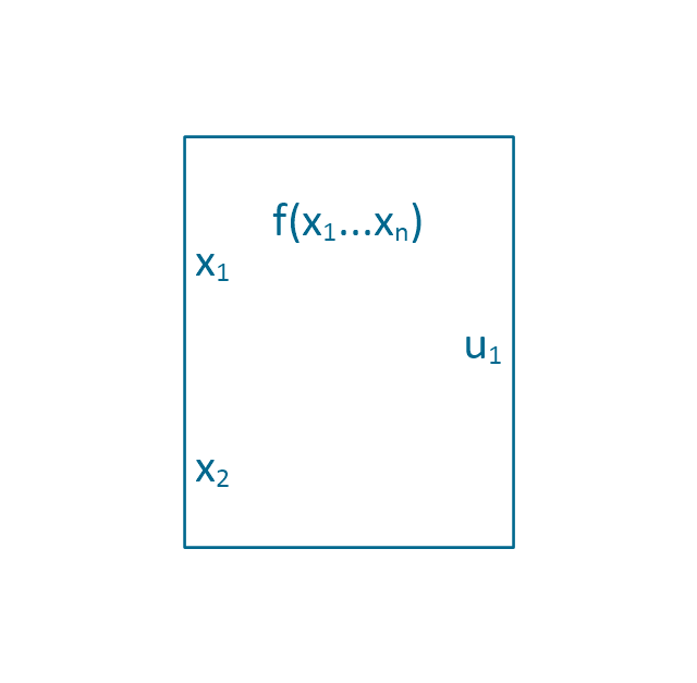
Function generator
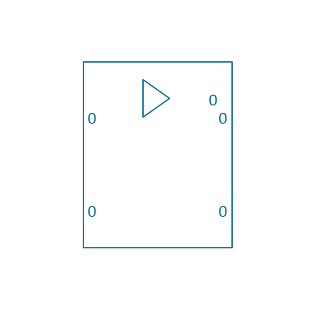
Amplifier
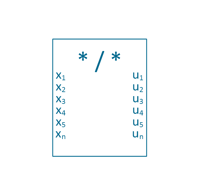
Converter
Logic gates
Inverter
Inverter 2
Buffer
Buffer 2
RS Flip-flop
JK Flip-flop
Latch Flip-flop
D Flip-flop
Analog symbol
Digital symbol
Negative logic dot
Potentiometer
Potentiometer 2
Positional servo
Piezoelectric crystal, 4 electrodes
Piezoelectric crystal, 3 electrodes
Piezoelectric crystal, 2 electrodes
I/O port bidirectional
I/O port unidirectional
Square signal
Sine wave signal
Sawtooth signal
Ramp signal
3 state data signal
Three-state buffer
Integrator
Summing amplifier
Multiplier
Divider
Function generator 2
Generalized integrator
Operational amplifier
Operational amplifier 2
Switch point
Switch point 2
The vector stencils library "Cisco optical" contains 19 symbols of optical devices for drawing Cisco computer network diagrams.
"Fiber-optic communication is a method of transmitting information from one place to another by sending pulses of light through an optical fiber. The light forms an electromagnetic carrier wave that is modulated to carry information. ... Because of its advantages over electrical transmission, optical fibers have largely replaced copper wire communications in core networks in the developed world. Optical fiber is used by many telecommunications companies to transmit telephone signals, Internet communication, and cable television signals. ...
The process of communicating using fiber-optics involves the following basic steps: Creating the optical signal involving the use of a transmitter, relaying the signal along the fiber, ensuring that the signal does not become too distorted or weak, receiving the optical signal, and converting it into an electrical signal." [Fiber-optic communication. Wikipedia]
The symbols example "Cisco optical - Vector stencils library" was created using the ConceptDraw PRO diagramming and vector drawing software extended with the Cisco Network Diagrams solution from the Computer and Networks area of ConceptDraw Solution Park.
www.conceptdraw.com/ solution-park/ computer-networks-cisco
Automatic Protection Switching (APS)
-cisco-optical---vector-stencils-library.png--diagram-flowchart-example.png)
Channelized pipe

Concatenated payload

Optical cross-connect

WDM

Optical fiber

ONS 15104

SONET MUX

Optical amplifier

Digitall cross-connect

Optical services router

Cisco 10700

Optical transport

Wide Area Application Engine (WAE)
-cisco-optical---vector-stencils-library.png--diagram-flowchart-example.png)
Protected optical

Unprotected optical

Metro 1500

ONS 15500

Pipe

What Is a Wireless Network?

The vector stencils library "Computers and network isometric" contains 56 3D clipart images of computer and network devices and equipment for drawing network diagrams.
The clip art example "Computers and network isometric - Vector stencils library" was created using the ConceptDraw PRO diagramming and vector drawing software extended with the Computer and Networks solution from the Computer and Networks area of ConceptDraw Solution Park.
The clip art example "Computers and network isometric - Vector stencils library" was created using the ConceptDraw PRO diagramming and vector drawing software extended with the Computer and Networks solution from the Computer and Networks area of ConceptDraw Solution Park.
Laptop
DDCS
Server
Webcam
Wireless Network Storage
Personal computer
VoIP phone
Fax
Plotter
Mobile phone
Feature phone
Printer
Satellite dish
Satellite antenna
Automatic-tracking satellite dish
Wireless access point
Wireless router
Router
Network switch
Network device
Mobile GPS Terminal
GPS phone
Television antenna
Radio tower
Base station
Satellite
In-vehicle satellite telecommunication
Satellite dishes on ship
Airplane
Internet
Man
Woman
Call-center
Honeycomb
Mountain
Radio waves
Radio waves
Tower block
Office building
House
House
Globe
Wireless security camera
Truck
Tree
Conifer tree
1U hub / switch
2U hub / switch
1U server
2U Server
3U Server
4U Server
Communications satellite
Car
Radio waves
Firewall
The vector stencils library "Southern constellations" contains 22 icons of Southern constellations maps.
Use these star constellation charts for drawing astronomical diagrams and illustrations in ConceptDraw PRO diagramming and vector drawing software extended with the Astronomy solution from the Science and Education area in ConceptDraw Solution Park.
Use these star constellation charts for drawing astronomical diagrams and illustrations in ConceptDraw PRO diagramming and vector drawing software extended with the Astronomy solution from the Science and Education area in ConceptDraw Solution Park.
Apus
---vector-stencils-library.png--diagram-flowchart-example.png)
Ara
---vector-stencils-library.png--diagram-flowchart-example.png)
Carina
---vector-stencils-library.png--diagram-flowchart-example.png)
Chamaeleon
---vector-stencils-library.png--diagram-flowchart-example.png)
Circinus
---vector-stencils-library.png--diagram-flowchart-example.png)
Crux
---vector-stencils-library.png--diagram-flowchart-example.png)
Dorado
---vector-stencils-library.png--diagram-flowchart-example.png)
Horologium
---vector-stencils-library.png--diagram-flowchart-example.png)
Hydrus
---vector-stencils-library.png--diagram-flowchart-example.png)
Indus
---vector-stencils-library.png--diagram-flowchart-example.png)
Mensa
---vector-stencils-library.png--diagram-flowchart-example.png)
Musca
---vector-stencils-library.png--diagram-flowchart-example.png)
Norma
---vector-stencils-library.png--diagram-flowchart-example.png)
Octans
---vector-stencils-library.png--diagram-flowchart-example.png)
Pavo
---vector-stencils-library.png--diagram-flowchart-example.png)
Phoenix
---vector-stencils-library.png--diagram-flowchart-example.png)
Pictor
---vector-stencils-library.png--diagram-flowchart-example.png)
Reticulum
---vector-stencils-library.png--diagram-flowchart-example.png)
Telescopium
---vector-stencils-library.png--diagram-flowchart-example.png)
Triangulum Australe
---vector-stencils-library.png--diagram-flowchart-example.png)
Tucana
---vector-stencils-library.png--diagram-flowchart-example.png)
Volans
---vector-stencils-library.png--diagram-flowchart-example.png)
Electrical Symbols — Delay Elements

Cisco WAN. Cisco icons, shapes, stencils and symbols
")
Using Both Wired and Wireless Connections

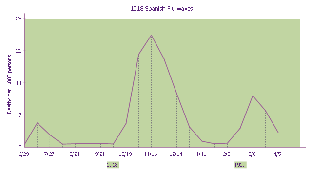
This line graph sample shows three pandemic waves: weekly combined influenza and pneumonia mortality, United Kingdom, 1918–1919. It was designed on the base of the Wikimedia Commons file: 1918 spanish flu waves.gif. [commons.wikimedia.org/ wiki/ File:1918_ spanish_ flu_ waves.gif]
"The 1918 flu pandemic (January 1918 – December 1920) was an unusually deadly influenza pandemic, the first of the two pandemics involving H1N1 influenza virus. It infected 500 million people across the world, including remote Pacific islands and the Arctic, and resulted in the deaths of 50 to 100 million (three to five percent of the world's population), making it one of the deadliest natural disasters in human history." [1918 flu pandemic. Wikipedia]
The line chart example "1918 Spanish Flu waves" was created using the ConceptDraw PRO diagramming and vector drawing software extended with the Line Graphs solution from the Graphs and Charts area of ConceptDraw Solution Park.
Line chart
Network Printer


- Lake Wave Vector
- Red Signal Wave Vector Png
- Radar Wave Vector Png
- Sound Wave Vector Png
- Wave Vector Radio
- Sine Wave Vector
- Electric Waves Vector
- Audio - Vector stencils library | How To use House Electrical Plan ...
- ConceptDraw Arrows10 Technology | Audio - Vector stencils library ...
- Audio - Vector stencils library
- Portable Speaker Vector Png
- Audio - Vector stencils library | Cisco telepresence - Vector stencils ...
- Radar Waves
- Vector Sound System Png
- Telecommunication networks - Vector stencils library | Computers ...
- Telecommunication networks - Vector stencils library ...
- Audio - Vector stencils library | Design elements - Lamps, acoustics ...
- Audio - Vector stencils library | Design elements - Video and audio ...
- Audio - Vector stencils library
- Mixer Radio Vector Png