The vector stencils library "Analog and digital logic" contains 40 element symbols of logic (threshold) gates, bistable current switches, current controllers, regulators, electrical generators, and amplifiers.
Use it for drawing the digital and analog functions in electronic circuit diagrams and electrical schematics in the ConceptDraw PRO diagramming and vector drawing software extended with the Electrical Engineering solution from the Engineering area of ConceptDraw Solution Park.
www.conceptdraw.com/ solution-park/ engineering-electrical
Clock
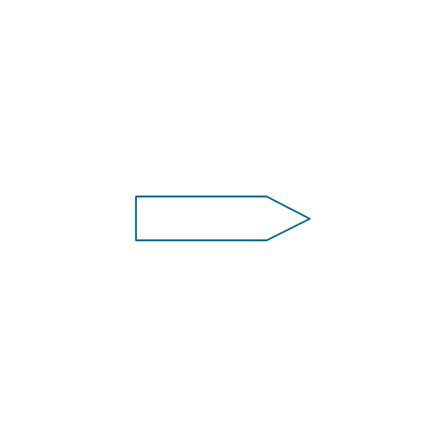
Function generator
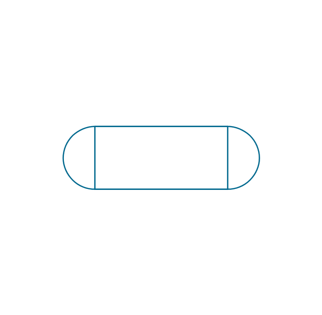
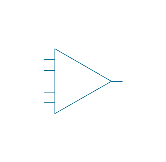
Amplifier
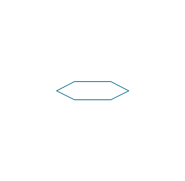
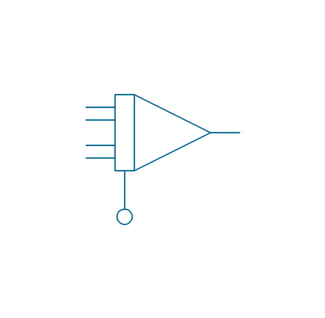
Converter
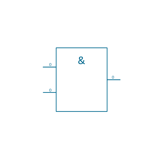
Logic gates
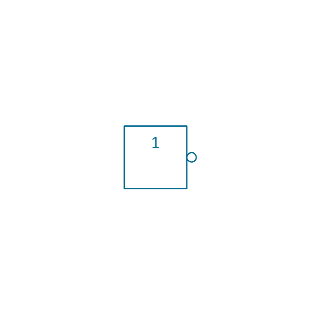
Inverter

Inverter 2
Buffer

Buffer 2

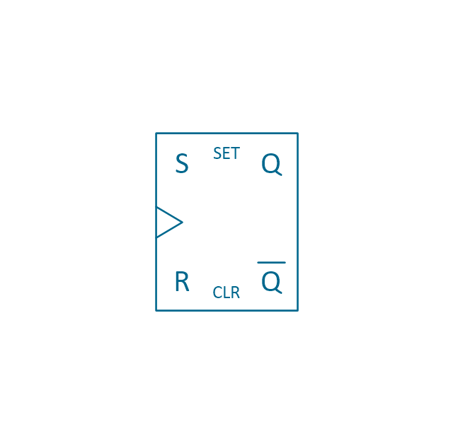
RS Flip-flop
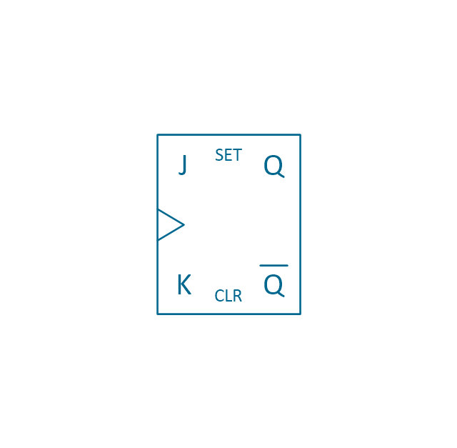
JK Flip-flop
Latch Flip-flop
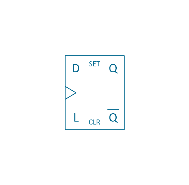
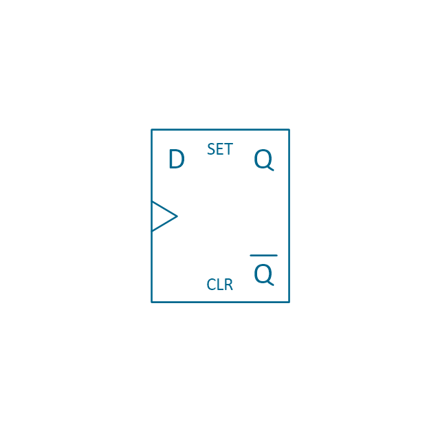
D Flip-flop
Analog symbol

Digital symbol

Negative logic dot

Potentiometer
Potentiometer 2
Positional servo
Piezoelectric crystal, 4 electrodes

Piezoelectric crystal, 3 electrodes

Piezoelectric crystal, 2 electrodes

I/O port bidirectional
I/O port unidirectional
Square signal

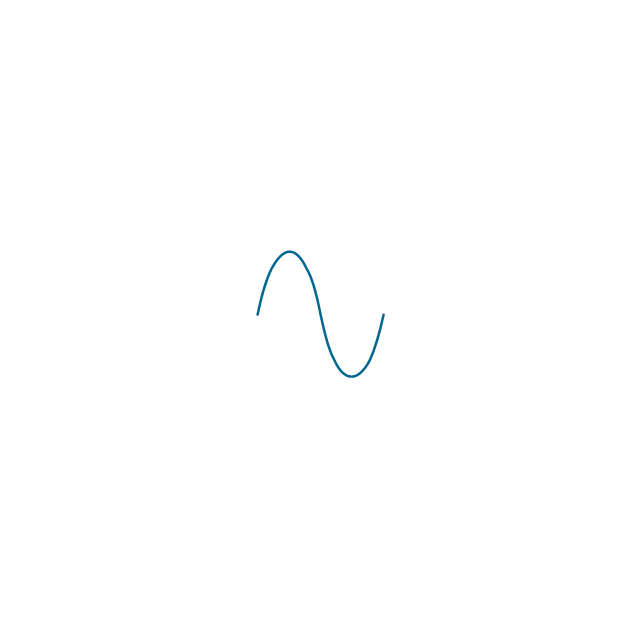
Sine wave signal
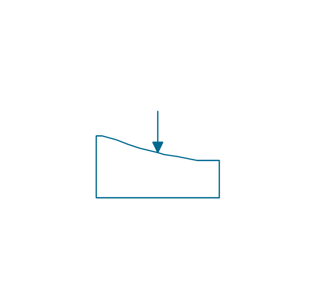
Sawtooth signal

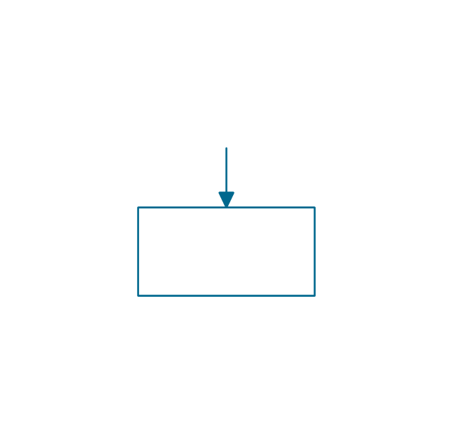
Ramp signal
3 state data signal

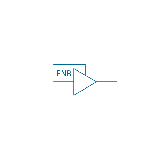
Three-state buffer
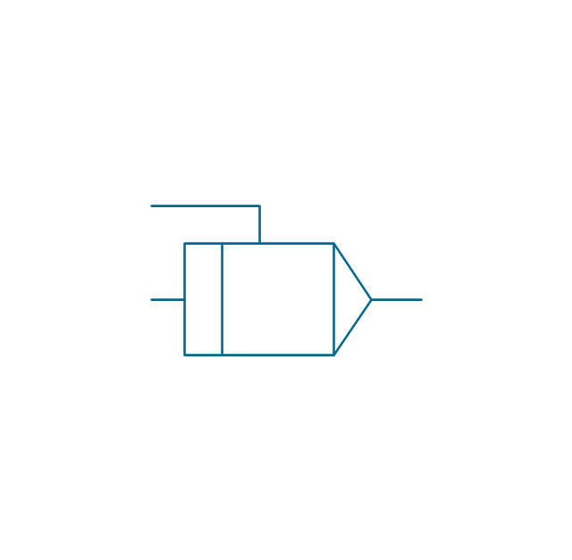
Integrator
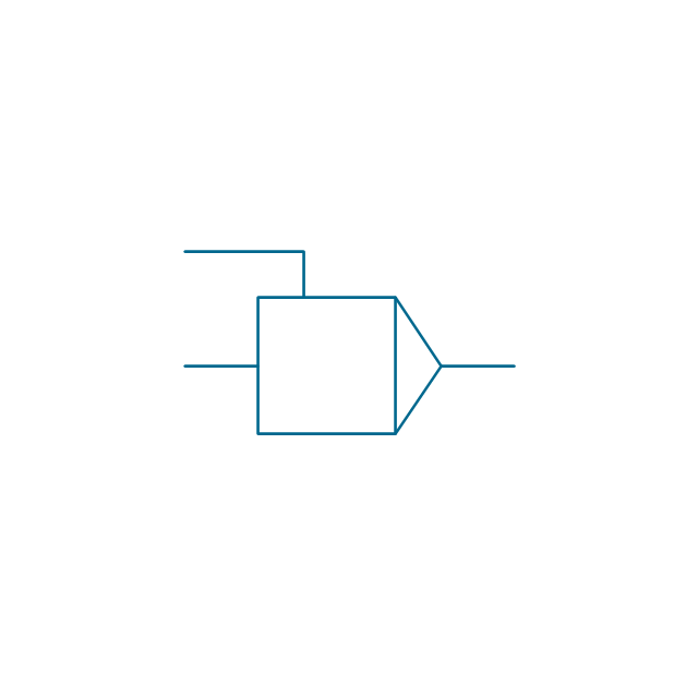
Summing amplifier
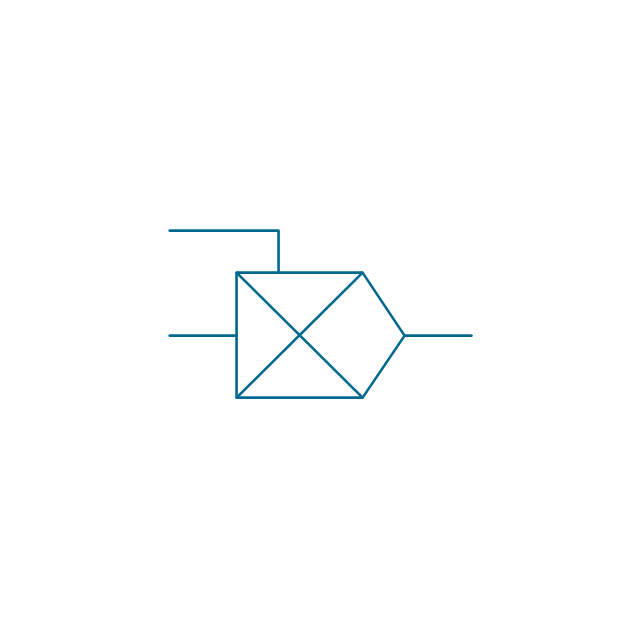
Multiplier
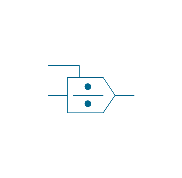
Divider
Function generator 2
Generalized integrator
Operational amplifier

Operational amplifier 2
Switch point
Switch point 2

The vector stencils library "Analog and digital logic" contains 40 element symbols of logic (threshold) gates, bistable current switches, current controllers, regulators, electrical generators, and amplifiers.
Use it for drawing the digital and analog functions in electronic circuit diagrams and electrical schematics in the ConceptDraw PRO diagramming and vector drawing software extended with the Electrical Engineering solution from the Engineering area of ConceptDraw Solution Park.
www.conceptdraw.com/ solution-park/ engineering-electrical
Use it for drawing the digital and analog functions in electronic circuit diagrams and electrical schematics in the ConceptDraw PRO diagramming and vector drawing software extended with the Electrical Engineering solution from the Engineering area of ConceptDraw Solution Park.
www.conceptdraw.com/ solution-park/ engineering-electrical
Clock
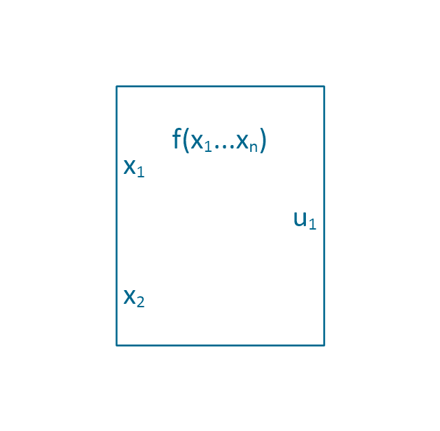
Function generator
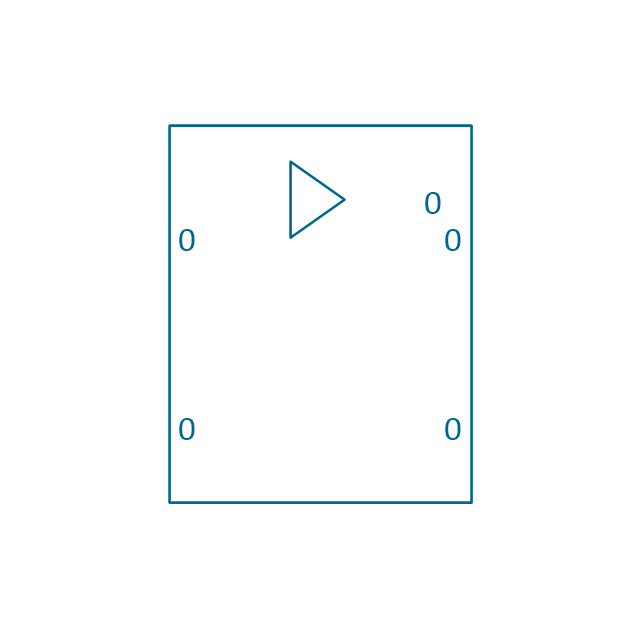
Amplifier
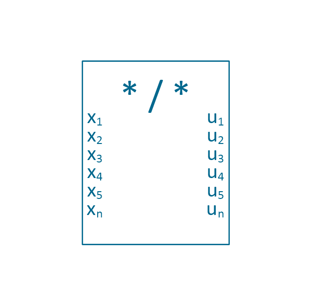
Converter
Logic gates
Inverter
Inverter 2
Buffer
Buffer 2
RS Flip-flop
JK Flip-flop
Latch Flip-flop
D Flip-flop
Analog symbol
Digital symbol
Negative logic dot
Potentiometer
Potentiometer 2
Positional servo
Piezoelectric crystal, 4 electrodes
Piezoelectric crystal, 3 electrodes
Piezoelectric crystal, 2 electrodes
I/O port bidirectional
I/O port unidirectional
Square signal
Sine wave signal
Sawtooth signal
Ramp signal
3 state data signal
Three-state buffer
Integrator
Summing amplifier
Multiplier
Divider
Function generator 2
Generalized integrator
Operational amplifier
Operational amplifier 2
Switch point
Switch point 2
Electrical Symbols — Analog and Digital Logic

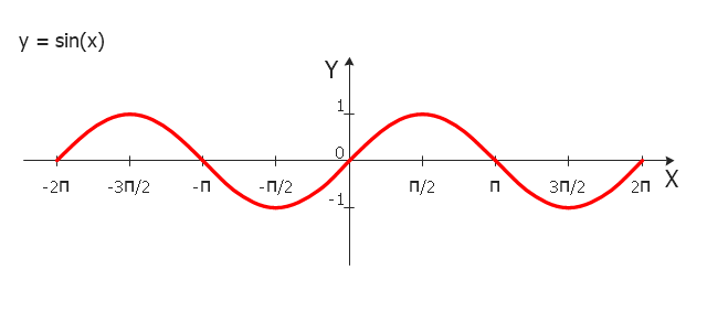
"In mathematics, the sine function is a trigonometric function of an angle. The sine of an angle is defined in the context of a right triangle: for the specified angle, it is the ratio of the length of the side that is opposite that angle to (divided by) the length of the longest side of the triangle (i.e. the hypotenuse).
Trigonometric functions are commonly defined as ratios of two sides of a right triangle containing the angle, and can equivalently be defined as the lengths of various line segments from a unit circle. More modern definitions express them as infinite series or as solutions of certain differential equations, allowing their extension to arbitrary positive and negative values and even to complex numbers.
The sine function is commonly used to model periodic phenomena such as sound and light waves, the position and velocity of harmonic oscillators, sunlight intensity and day length, and average temperature variations throughout the year." [Sine. Wikipedia]
The trigonometric function graph example "Sine function" was created using the ConceptDraw PRO diagramming and vector drawing software extended with the Mathematics solution from the Science and Education area of ConceptDraw Solution Park.
Sine function graph
SysML

UML Block Diagram

UML Diagram Types List

UML Flowchart Symbols

 SYSML
SYSML
The SysML solution helps to present diagrams using Systems Modeling Language; a perfect tool for system engineering.
- Sine Waves Vector Png
- Analog and digital logic - Vector stencils library
- Sine Wave Logo
- Wave Signal Vector
- Analog and digital logic - Vector stencils library | Analog and digital ...
- Analog and digital logic - Vector stencils library | Audio - Vector ...
- Vectors Waves Png
- Analog and digital logic - Vector stencils library | Design elements ...
- Analog and digital logic - Vector stencils library | Flowchart - Vector ...
- Analog and digital logic - Vector stencils library | Computers and ...
- Analog and digital logic - Vector stencils library | Electrical Symbols ...
- Electrical Symbols — Analog and Digital Logic | Analog and digital ...
- Analog and digital logic - Vector stencils library | How To use House ...
- UML Activity Diagram. Design Elements | Analog and digital logic ...
- Electrical Symbols — Logic Gate Diagram | Analog and digital logic ...
- Electrical Symbols — Analog and Digital Logic | Audio - Vector ...
- Logic gate diagram - Vector stencils library | Design elements ...
- Glyph icons - Vector stencils library | Analog and digital logic ...
- Electrical Symbols — Delay Elements | Analog and digital logic ...
- Logic gate diagram - Vector stencils library | Electrical Symbols ...