Example of DFD for Online Store (Data Flow Diagram) DFD Example


Flowchart design. Flowchart symbols, shapes, stencils and icons


Plant Design

UML Component Diagram


Network Diagrams for Bandwidth Management


The vector stencils library "Landmarks" contains 69 landmark symbols of buildings, waterways, scale and directional indicators for labeling transportation and directional maps, road and route maps, street and transit maps, locator and tourist maps.
The pictograms example "Landmarks - Vector stencils library" was created using the ConceptDraw PRO diagramming and vector drawing software extended with the Directional Maps solution from the Maps area of ConceptDraw Solution Park.
The pictograms example "Landmarks - Vector stencils library" was created using the ConceptDraw PRO diagramming and vector drawing software extended with the Directional Maps solution from the Maps area of ConceptDraw Solution Park.
Viewpoint

North arrow
North arrow
Building

Building

Town house

Suburban home

Skyscraper

Town hall

Public house

Petrol station

Gas station

Factory

School

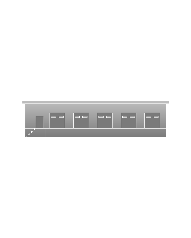
Warehouse
Hospital

Fire station

Train station

Condos

Barn

Motel

Convenience store

Shopping centre

City

Church

Cathedral

National tail train station

Train railway

Bus stop

Tramlink

Marina / Ferry dock

Car ferry

Stop light

Airport

Airport

Underground / Subway / Metro

Taxi

Bicycle parking

Parking

Fuel / Gas / Petrol

Police

Hospital

Wheelchair access

First aid

Telephone

Post office

Landmarks and museums

University

Shopping

Refreshments / Public House

Restrooms / Toilets

Park

Zoo

Information center

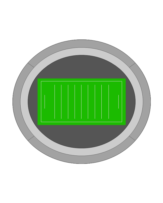
Stadium 1
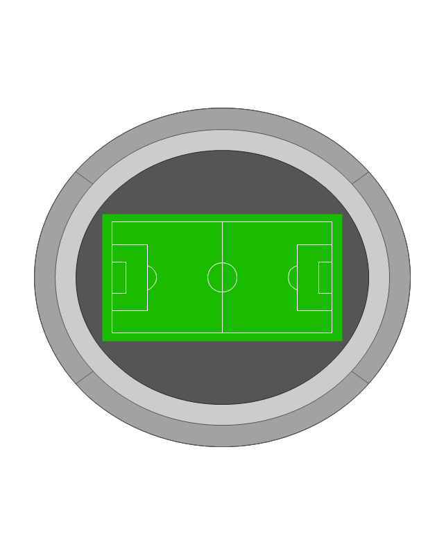
Stadium 2
Park

Tree

Fir-tree

Ocean

Lake

River

Angled river

Forked river

Curved river

Curved river

Flexible river

Bridge

Scale
 Data Flow Diagrams (DFD)
Data Flow Diagrams solution extends ConceptDraw PRO software with templates, samples and libraries of vector stencils for drawing the data flow diagrams (DFD).
 AWS Architecture Diagrams
AWS Architecture Diagrams with powerful drawing tools and numerous predesigned Amazon icons and AWS simple icons is the best for creation the AWS Architecture Diagrams, describing the use of Amazon Web Services or Amazon Cloud Services, their application for development and implementation the systems running on the AWS infrastructure. The multifarious samples give you the good understanding of AWS platform, its structure, services, resources and features, wide opportunities, advantages and benefits from their use; solution’s templates are essential and helpful when designing, description and implementing the AWS infrastructure-based systems. Use them in technical documentation, advertising and marketing materials, in specifications, presentation slides, whitepapers, datasheets, posters, etc.
UML Class Diagram Example - Medical Shop

 Cross-Functional Flowcharts
Cross-functional flowcharts are powerful and useful tool for visualizing and analyzing complex business processes which requires involvement of multiple people, teams or even departments. They let clearly represent a sequence of the process steps, the order of operations, relationships between processes and responsible functional units (such as departments or positions).
- A Complete Flowchart Of Distribution Design Of Any Shopping Mall
- Shopping Mall Design Download Software
- Bubble Diagram For A Shopping Complex
- Mini Shopping Mall Floor Plan
- A Floor Plan On Mini Shopping Complex
- Factory layout floor plan | Store Layout Software | Plant Layout Plans ...
- Simple Shopping Mall Floor Plan
- Shopping Mall Blueprints
- Shopping Mall Plan Drawings Pdf