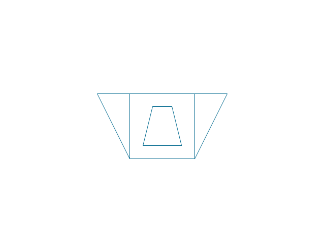
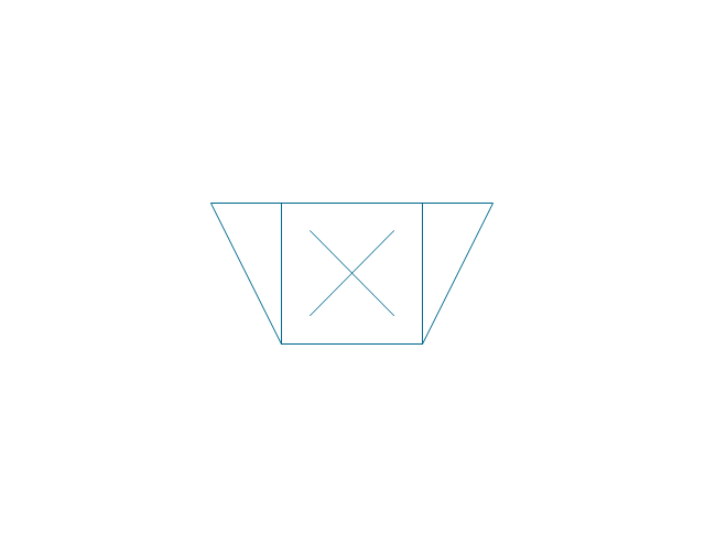
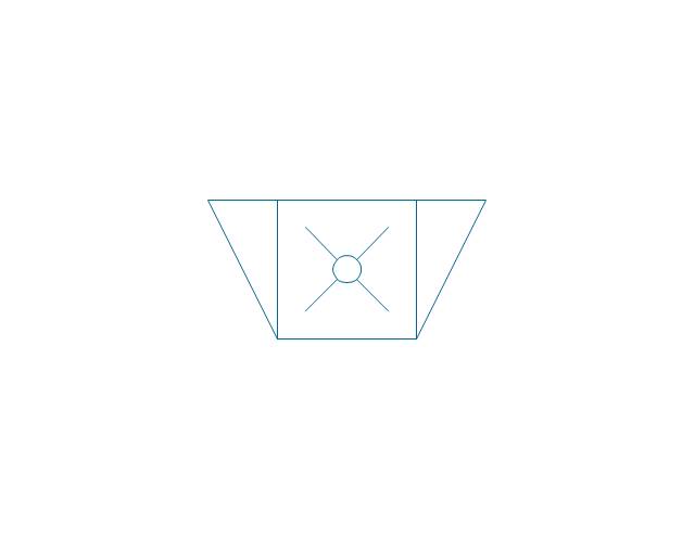
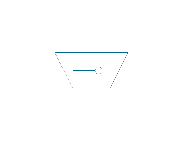
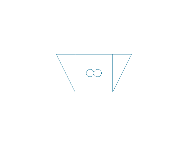
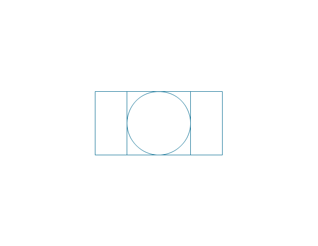
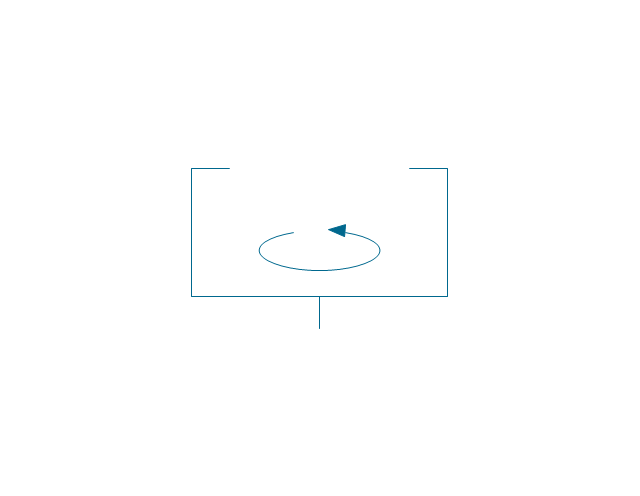
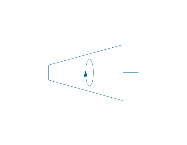
The vector stencils library "Chemical engineering" contains 24 symbols of chemical and process engineering equipment.
Use these shapes for drawing Process Flow Diagrams (PFD), Piping and Instrumentation Diagrams (P&ID), and Water Flow Diagrams in the ConceptDraw PRO software extended with the Chemical and Process Engineering solution from the Chemical and Process Engineering area of ConceptDraw Solution Park.
www.conceptdraw.com/ solution-park/ engineering-chemical-process
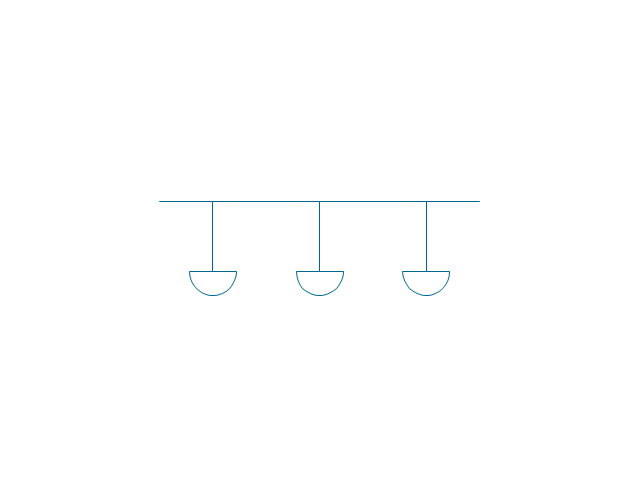
Clarifier

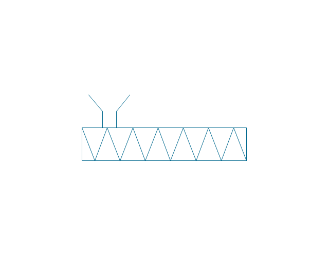
Screen

Filter

Agitator

Vapor 1

Vapor 2

Vessel

Pump mixer

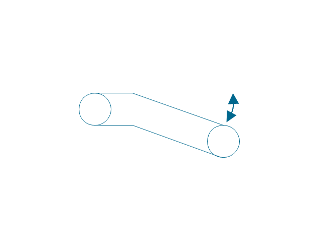
Centrifugal pump

Fan

Blower

Evaporator

Tower

Flash drum

Roll press

Cooling tower

Tank car

Tank truck

Kettle

Valve

Motor valve

Venturi

Propeller

Instrument

 Chemical and Process Engineering
Extending the ConceptDraw DIAGRAM diagramming and drawing software with process flow diagram symbols, samples, process diagrams templates and libraries of design elements for creating process and instrumentation diagrams, block flow diagrams, process flow diagrams, and piping and instrumentation diagrams for chemical and process engineering, the Chemical and Process Engineering solution can be used by both chemical and project engineers, as well as the chemists for creating the needed drawings.
Process Engineering

The vector stencils library "Instruments" contains 72 symbols of control instruments and measuring devices: meters and gauges, and callouts, text boxes, and inserts.
Use these shapes to create annotated process flow diagrams (PFD), flow control, manufacturing processes, and distribution system diagrams in the ConceptDraw PRO software extended with the Chemical and Process Engineering solution from the Chemical and Process Engineering area of ConceptDraw Solution Park.
www.conceptdraw.com/ solution-park/ engineering-chemical-process
Indicator local

Indicator remote

Indicator auxiliary

CRT local

CRT remote

CRT auxiliary

PLC local

PLC auxiliary

PLC remote

Computer local

Computer auxiliary

Computer remote

Light local

Light remote

Light auxiliary

Indicator auxiliary (dashed)
-instruments---vector-stencils-library.png--diagram-flowchart-example.png)
Indicator remote (dashed)
-instruments---vector-stencils-library.png--diagram-flowchart-example.png)
Steam traced auxiliary

Steam traced remote

Steam traced local

Level meter auxiliary

Level meter remote

Level meter local

Pressure gauge diaphragm

Pressure gauge

Pressure gauge liquid filled

Strain gauge

Thermometer bi-metallic

Thermometer gas

Thermometer general

Thermometer glass

Thermometer liquid

Thermometer resistance

Thermometer thermocouple

Flowmeter electromagnetic

Flowmeter general

Flowmeter nozzle

Flowmeter orifice

Flowmeter positive displacement

Flowmeter turbine

Flowmeter variable area

Flowmeter Venturi

Level meter capacitive

Level meter conductive

Level meter displacer

Level meter float

Level meter general

Level meter sonic

Indicator analoque

Indicator digital

Indicator general

Recorder analoque

Recorder digital

Recorder general

Converter

Converter 2 (1st half filled)
-instruments---vector-stencils-library.png--diagram-flowchart-example.png)
Converter 3 (2nd half filled)
-instruments---vector-stencils-library.png--diagram-flowchart-example.png)
Venturi

Venturi (pressure taps)
-instruments---vector-stencils-library.png--diagram-flowchart-example.png)
Flowmeter

Rotameter

Vortex sensor

Propeller meter

Generic utility

Operator box

Operator box 2 (1st half filled)
-instruments---vector-stencils-library.png--diagram-flowchart-example.png)
Operator box 3 (2nd half filled)
-instruments---vector-stencils-library.png--diagram-flowchart-example.png)
AND gate

OR gate

NOT gate

Correcting element

Diamond

The vector stencils library "Industrial equipment" contains 81 symbols of pumps, compressors, fans, turbines, and power generators.
Use these shapes to design pumping systems, air and fluid compression systems, and industrial process diagrams in the ConceptDraw PRO software extended with the Chemical and Process Engineering solution from the Chemical and Process Engineering area of ConceptDraw Solution Park.
www.conceptdraw.com/ solution-park/ engineering-chemical-process
Breaker

Crusher

Crusher coarse

Crusher medium

Crusher fine

Roll crusher

Hammer crusher

Crusher single load

Crusher hammer

Crusher impact

Crusher jaw

Crusher high-speed roller

Crusher cone

Crusher cone 2
Crusher general
Crusher hammer 2

Crusher impact 2
Crusher jaw 2
Crusher roller
Ball mill

Mill general

Mill hammer

Mill impact

Mill jet

Mill roller

Mill vibrator

Mixer

Mixer general

Mixer rotary

Mixer can

Mixer fluidized

Kneader

Kneader general

Kneader wheel

Kneader ball

Kneader rolling

Kneader blade

Blender

Double blender

Fluid separator general

Fluid separator wet

Fluid separator dry

Fluid separator gravitation

Fluid separator inertial

Fluid separator centrifugal

Filter 1
Filter 2

Rotary filter

Screen

Electromagnet

Cyclone 1

Cyclone 2

Centrifuge general

Centrifuge dehydrator
Centrifuge submersion
Centrifuge 2

Briquetting machine standard

Briquetting machine

Prill tower

Dryer

Conveyor 2 circles 2 lines

Conveyor 2 circles 1 line

Conveyor 1 circle 2 lines

Conveyor 1 circle 1 line

Conveyor wheel

Boom loader
Scraper conveyor

Screw conveyor
Screw conveyor 2

Elevator 1

Elevator 2

Skip hoist

Overhead conveyor

Overhead conveyor with hooks

Overhead conveyor with buckets
Hoist

Hoist with hook

Hoist with grab

Electric motor

Tank truck

Tank car

The vector stencils library "Heating equipment" contains 42 symbols of regenerators, intercoolers, heaters, and condensers.
Use these shapes for drawing cooling systems, heat recovery systems, thermal, heat transfer and mechanical design, and process flow diagrams (PFD) in the ConceptDraw PRO software extended with the Chemical and Process Engineering solution from the Chemical and Process Engineering area of ConceptDraw Solution Park.
www.conceptdraw.com/ solution-park/ engineering-chemical-process
Heat exchanger 3

Heat exchanger 1

Heat exchanger 2

Tube bundle, floating head

U-Tube bundle

Tube bundle

Shell and tube

Kettle reboiler

Plate type

Finned tube

Double pipe type

Oil burner

Boiler

Fired heater

Cooling tower 2

Cooling tower 1

Cooling tower 3

Condenser

Automatic stoker

Refrigerator

Direct refrigerator

Indirect refrigerator

Evaporative condenser

Condenser (air cooled)
-heating-equipment---vector-stencils-library.png--diagram-flowchart-example.png)
Oil separator

Chilling evaporator

Air cooling evaporator

Extractor hood (slot)
-heating-equipment---vector-stencils-library.png--diagram-flowchart-example.png)
Extractor hood (open)
-heating-equipment---vector-stencils-library.png--diagram-flowchart-example.png)
Autoclave (propeller)
-heating-equipment---vector-stencils-library.png--diagram-flowchart-example.png)
Autoclave (anchor)
-heating-equipment---vector-stencils-library.png--diagram-flowchart-example.png)
Autoclave (helical)
-heating-equipment---vector-stencils-library.png--diagram-flowchart-example.png)
Autoclave with motor (helical)
-heating-equipment---vector-stencils-library.png--diagram-flowchart-example.png)
Autoclave with motor (anchor)
-heating-equipment---vector-stencils-library.png--diagram-flowchart-example.png)
Autoclave with motor (propeller)
-heating-equipment---vector-stencils-library.png--diagram-flowchart-example.png)
Fan blades horizontal

Fan blades vertical

Fan blades (4)
-heating-equipment---vector-stencils-library.png--diagram-flowchart-example.png)
Triple fan blades

Air-blown cooler

Condenser

Heater / Cooler

Cisco Optical. Cisco icons, shapes, stencils and symbols

The vector stencils library "Pumps" contains 82 symbols of pumps, compressors, fans, turbines, and power generators.
Use these icons to design pumping systems, air and fluid compression systems, and industrial process diagrams in the ConceptDraw PRO software extended with the Chemical and Process Engineering solution from the Chemical and Process Engineering area of ConceptDraw Solution Park.
www.conceptdraw.com/ solution-park/ engineering-chemical-process
In-line pump

In-line pump 2

Positive displacement

Centrifugal pump (arrows)
-pumps---vector-stencils-library.png--diagram-flowchart-example.png)
Centrifugal pump

Rotary pump 1

Rotary pump 2

Proportioning pump

Pump vacuum

Pump positive displacement

Pump piston

Pump liquid ring

Pump oil-sealed rotary (single)
-pumps---vector-stencils-library.png--diagram-flowchart-example.png)
Pump oil-sealed rotary (multi)
-pumps---vector-stencils-library.png--diagram-flowchart-example.png)
Pump roots

Pump gas ballast

Pump turbo molecular

Pump general

Pump centrifugal

Pump positive displacement 2

Pump gear

Pump screw

Pump helical rotor

Pump reciprocating

Pump diaphragm

Pump liquid jet

Pump centrifugal 2

Pump diaphragm 2

Pump gear 2

Pump general 2

Pump helical rotor 2

Pump reciprocating 2

Pump screw 2

Compressor general

Compressor container

Compressor rotary

Compressor screw

Compressor reciprocating

Compressor ejector

Compressor general 2

Compressor liquid ring

Compressor positive displacement

Compressor reciprocating 2

Compressor reciprocating diaphragm

Compressor roller vane

Compressor rotary 2

Compressor screw 2

Compressor turbo

Compressor general 3

Compressor reciprocating 3

Compressor reciprocating diaphragm 2

Compressor roller vane 2

Compressor rotary 3

Compressor screw 3

Rotary compressor

Motor driven turbine

Compressor (center line)
-pumps---vector-stencils-library.png--diagram-flowchart-example.png)
Compressor

Turbine

Turbine (center line)
-pumps---vector-stencils-library.png--diagram-flowchart-example.png)
Reciprocating pump/compressor

Reciprocating pump 2

Fan general

Fan radial

Fan axial

Fan general 2

Fan radial 2

Fan axial 2

Centrifugal fan 2 (center circle)
-pumps---vector-stencils-library.png--diagram-flowchart-example.png)
Centrifugal fan

Axial flow fan supply

Axial flow fan exhaust

Axial flow fan exhaust wall-type

Axial flow fan supply wall-type

Axial flow fan 2

Ejector / injector

Spray

Shower

Fan blades horizontal

Fan blades vertical

Fan blades (4)
-pumps---vector-stencils-library.png--diagram-flowchart-example.png)
Triple fan blades

The vector stencils library "Vessels" contains 40 symbols of vessels, containers, tanks, drums, and basins.
Use these shapes for drawing process flow diagrams (PFD), materials handling systems, and feed systems in industrial and manufacturing processes.
"A pressure vessel is a closed container designed to hold gases or liquids at a pressure substantially different from the ambient pressure.
The pressure differential is dangerous and fatal accidents have occurred in the history of pressure vessel development and operation. Consequently, pressure vessel design, manufacture, and operation are regulated by engineering authorities backed by legislation. For these reasons, the definition of a pressure vessel varies from country to country, but involves parameters such as maximum safe operating pressure and temperature." [Pressure vessel. Wikipedia]
The example "Design elements - Vessels" was created using the ConceptDraw PRO diagramming and vector drawing software extended with the Chemical and Process Engineering solution from the Engineering area of ConceptDraw Solution Park.
Vessel symbols

CAD Software for Architectural Designs

Use the libraries with a set of vector objects, templates and samples from the Floor Plans Solution from the Building Plans area of ConceptDraw Solution Park for designing your professional architectural designs.
Chemical Process Flow Diagram

Process Flow Diagram

 Event-driven Process Chain Diagrams
Event-Driven Process Chain Diagrams solution extends ConceptDraw DIAGRAM functionality with event driven process chain templates, samples of EPC engineering and modeling the business processes. It includes a vector shape library for drawing the EPC diagrams and EPC flowcharts of any complexity. It is one of EPC IT solutions that assist the marketing experts, business specialists, engineers, educators and researchers in resources planning and improving the business processes using the EPC flowchart or EPC diagram. Use the EPC solutions tools to construct the chain of events and functions, to illustrate the structure of a business process control flow, to describe people and tasks for execution the business processes. Apply it to identify the inefficient business processes in the enterprise and take the corresponding measures required to make them efficient.
 Cross-Functional Flowcharts
The Cross-Functional Flowcharts solution extends ConceptDraw DIAGRAM software with cross functional flowchart examples, samples, and libraries of cross functional flow chart vector design elements and CH-1 symbols for easy drawing professional-looking and illustrative Cross Functional Flowchart, Cross Functional Diagram, CH-1 Diagram, Process Flowchart, Deployment Flowchart, Opportunity Flowchart, Swimlane Process Mapping Diagram, or Visio Cross Functional Flowchart for planning and further analyzing, optimizing and improvement processes. The use of included pre-made cross functional flowchart template, opportunity flowchart template, and swimlane process map template, greatly easier designing your Cross-functional flowcharts.
Chemical Flow Chart

Process Flow Chart Symbols

 Electronic Block Diagrams
The Electronic Block Diagrams solution for ConceptDraw DIAGRAM includes a set of diagrams samples and a large number of specialized electronic and electrical symbols of electronic blocks, amplifiers, pulses, repeaters, converters, waveforms, electric filters, delay elements, etc. All symbols are highly simple and common for electronics. They allow designing strict and clear diagrams and electronics graphical designs for documentation, specifications, reports, presentation slides. Use them in electrical engineering, to design and construct electronic equipment, show sequence of pulses and flow of energy, and rapidly identify points of interest or trouble spots in electronic circuits.
Example Process Flow Chart

Flowchart Software


EPC Engineering

- Process Flow Diagram Symbols | Process Engineering
- Flowchart Software | Visio Engineering Stencils Free Download
- Process Flowchart | Visio Chemical Engineering Shapes Download
- Chemical and Process Engineering | Microsoft Visio Engineer Shapes
- Chemical and Process Engineering | Ms Visio Stencils Chemical
- Flowchart Software | Chemical Engineering | Visio Process ...
- Visio Process Engineering Sample
- Process Flow Diagram Symbols | Visio Chemical Engineering Shapes
- Process Flow Diagram Symbols | Visio Engineering Shapes
- Chemical engineering - Vector stencils library | Thickener Visio