HelpDesk
How to Set Line Jumps for Smart Connectors in ConceptDraw DIAGRAM

Basic Flowchart Symbols and Meaning


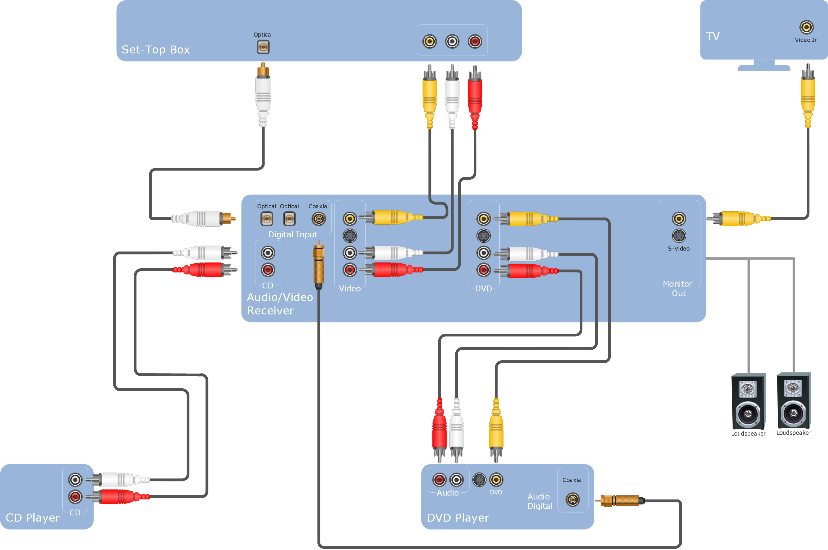
Audio Connectors

Electrical Symbols — Terminals and Connectors

HelpDesk
How to Add and Edit Connector Text

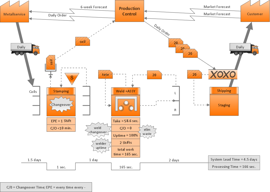
ConceptDraw Arrows10 Technology
HelpDesk
How To Create a Workflow Diagram in Visio

Entity Relationship Diagram Symbols

ConceptDraw Arrows10 Technology
- Visio Stencils Cable Connectors
- Wiring Diagrams with ConceptDraw PRO | Video Connectors | Audio ...
- Visio Vga Connector Shapes
- Visio Connector Straight Line
- Audio and video connectors - Vector stencils library
- Audio Visual Connectors Types | Audio and Video Connectors ...
- ConceptDraw PRO Compatibility with MS Visio | Terminals and ...
- Audio and video connectors - Vector stencils library | Conector Jack ...
- How to Add and Edit Text on Connectors | Basic Flowchart Symbols ...
- Visio Connector Routing