Electrical Symbols, Electrical Diagram Symbols

Electrical Drawing Software and Electrical Symbols

Electrical Symbols — Composite Assemblies

Electrical Symbols — Maintenance

Electrical Symbols — Stations

How To use House Electrical Plan Software


The vector stencils library "Electrical circuits" contains 49 element symbols of electrical and electronic devices, including ignitors, starters, transmitters, circuit protectors, transducers, radio and audio equipment.
Use it for drawing electronic circuit diagrams and electrical schematics in the ConceptDraw PRO diagramming and vector drawing software extended with the Electrical Engineering solution from the Engineering area of ConceptDraw Solution Park.
www.conceptdraw.com/ solution-park/ engineering-electrical
Ground

Equipotentiality

Igniter plug

Junction

Chassis

Chassis 2

Capacitor

Variable capacitor

Capacitor 2

Variable capacitor 2

Antenna

Antenna 2

Circuit breaker

Fuse

Fuse 2

Alarm fuse

Alarm fuse 2

Circular generic component

Rectangular generic component

Transducer

Capacitive transducer

Non-capacitive transducer

Recording pickup head

Reproducing pickup head

Positive pulse

Negative pulse

Alternating pulse

Saw tooth

Positive step function

Negative step function

Explosive squib

Sensing link squib

Squib ignitor

Unspecified material

Solid material

Semiconducting material

Liquid

Insulating material

Gas

Electret

Surge protector

Multigap surge protector

Valve surge protector

Electrolytic surge protector

Carbon block surge protector

Protective gap surge protector

Sphere gap surge protector

Horn gap surge protector

Circuit breaker

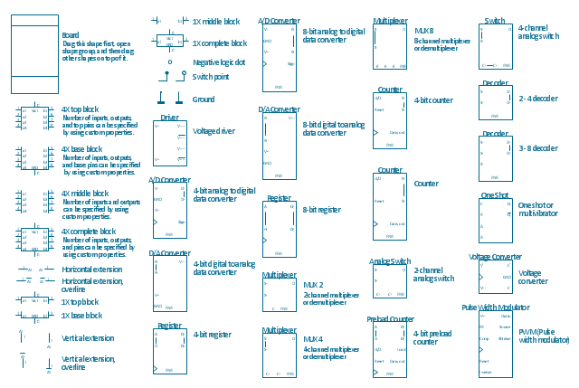
The vector stencils library "Integrated circuit" contains 43 component symbols: transducers, rotary devices, converters, registers, analog switches, counters, registers, decoders, and multiplex transmitters.
"An integrated circuit or monolithic integrated circuit (also referred to as an IC, a chip, or a microchip) is a set of electronic circuits on one small plate ("chip") of semiconductor material, normally silicon. This can be made much smaller than a discrete circuit made from independent components.
Integrated circuits are used in virtually all electronic equipment today and have revolutionized the world of electronics. Computers, mobile phones, and other digital home appliances are now inextricable parts of the structure of modern societies, made possible by the low cost of producing integrated circuits." [Integrated circuit. Wikipedia]
The symbols example "Design elements - Integrated circuit" was drawn using the ConceptDraw PRO diagramming and vector drawing software extended with the Electrical Engineering solution from the Engineering area of ConceptDraw Solution Park.
Integrated circuit components
Electrical Symbols — Transmission Paths
The vector stencils library "Electrical circuits" contains 49 element symbols of electrical and electronic devices, including ignitors, starters, transmitters, circuit protectors, transducers, radio and audio equipment.
Use it for drawing electronic circuit diagrams and electrical schematics.
"An electrical network is an interconnection of electrical elements such as resistors, inductors, capacitors, voltage sources, current sources and switches. An electrical circuit is a network consisting of a closed loop, giving a return path for the current. Linear electrical networks, a special type consisting only of sources (voltage or current), linear lumped elements (resistors, capacitors, inductors), and linear distributed elements (transmission lines), have the property that signals are linearly superimposable. They are thus more easily analyzed, using powerful frequency domain methods such as Laplace transforms, to determine DC response, AC response, and transient response.
A resistive circuit is a circuit containing only resistors and ideal current and voltage sources. Analysis of resistive circuits is less complicated than analysis of circuits containing capacitors and inductors. If the sources are constant (DC) sources, the result is a DC circuit.
A network that contains active electronic components is known as an electronic circuit. Such networks are generally nonlinear and require more complex design and analysis tools." [Electrical network. Wikipedia]
The symbils example "Design elements - Electrical circuits" was drawn using the ConceptDraw PRO diagramming and vector drawing software extended with the Electrical Engineering solution from the Engineering area of ConceptDraw Solution Park.
Electrical circuit elements

- Pressure Transmitter Schematic Symbol
- Symbol Of Transmitter
- Symbols Of Various Temperature Sensors Indicators And Transmitters
- Electronic Position Transmitter Symbol
- Fiber Optic Transmitter Schematic Symbol
- Temperature Transmitter Symbol
- Temperature Sensor Schematic Symbol
- Pressure Transmitter Electrical Symbol
- Symbol For Pressure Transducer On A Drawing
- Components And Symbols Of Transducers